Switching device actuated by a transponder

a technology of switching device and transponder, which is applied in the direction of anti-theft devices, near-field systems using receivers, instruments, etc., can solve the problems of large power supply not being available, unsuitable applications, and inability to take measures easily, and achieve cost-effective effects

Inactive Publication Date: 2005-07-21
AIRE TECH LTD
View PDF2 Cites 36 Cited by
  • Summary
  • Abstract
  • Description
  • Claims
  • Application Information

AI Technical Summary

Benefits of technology

[0010] Furthermore, the inventive device is very user-friendly because it requires no special handling at all on the part of the user. The transponders used have a conventional form of appearance and are used in the conventional way. The conventional design of the transponders used also has an advantageous effect on their manufacturing since special constructional measures regarding the structure are not required. One further advantage of the inventive device in particular is the fact that the coil which is already present in the transponder triggers the switching and therefore special components in the transponder are not required. Accordingly, the transponders can be of a cost-effective design.

Problems solved by technology

The regular production of magnetic field and interrogation signal causes a comparatively high energy consumption which renders the concept unsuitable for applications in which a sufficiently large power supply cannot be made available.
The installation of a permanent magnet requires constructional measures regarding the transponder elements to be equipped with such a magnet, and such measures cannot always be taken easily.
The mechanic integration is problem enough as to render the solution not suitable for, for example, contactless chip cards.
Furthermore, the magnetic field produced by a permanent magnet often is undesirable with regard to the practical usability of the transponders equipped with such permanent magnets.
The handling of such transponders is also restricted in so far as they have to be kept away from other circuits sensitive to magnetic fields.

Method used


Image

  • Switching device actuated by a transponder
  • Switching device actuated by a transponder
  • Switching device actuated by a transponder

Examples


Embodiment Construction

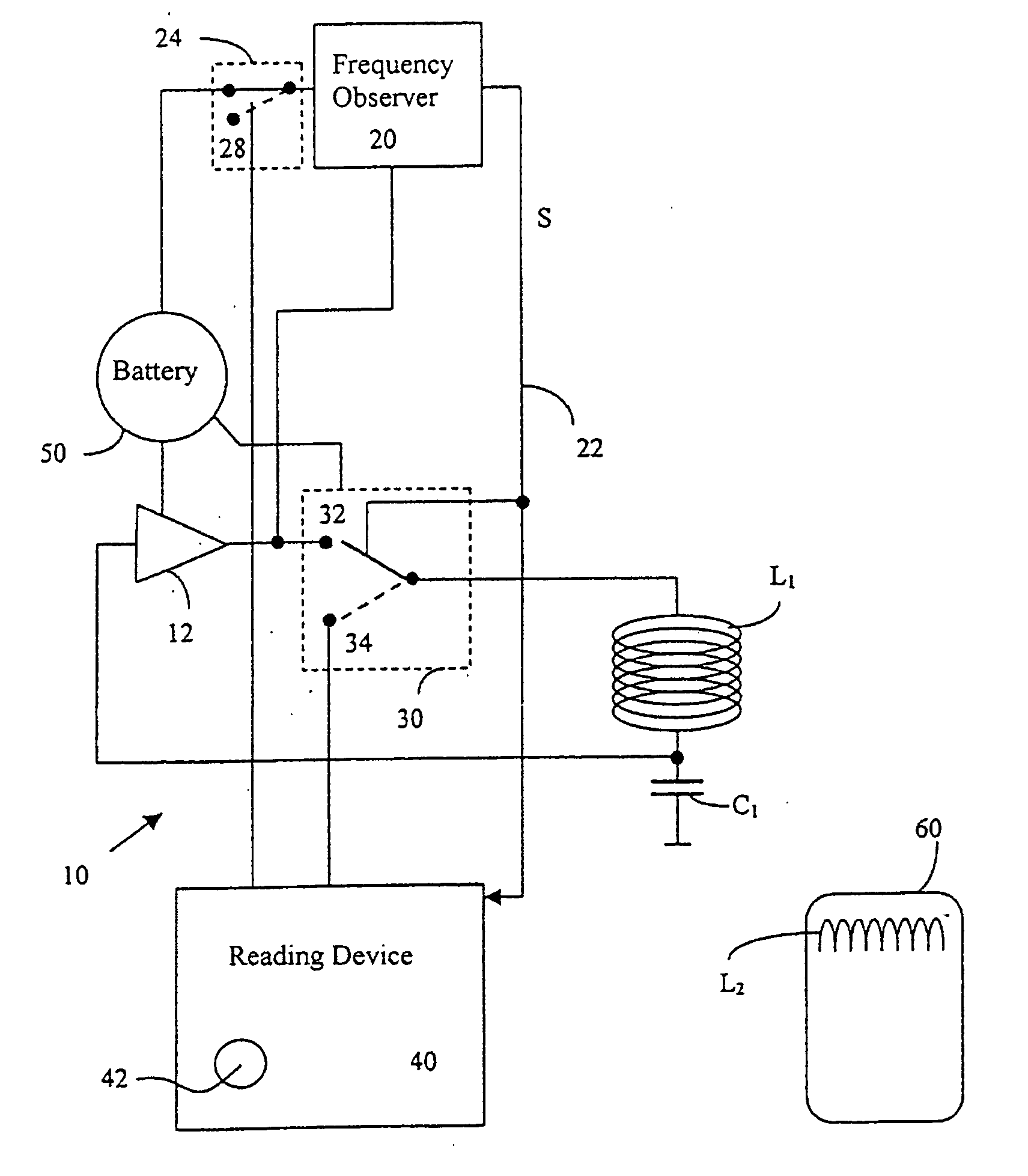
[0017] The basic elements of the switching device shown in FIG. 1 are an oscillating circuit 10, a frequency observer 20 connected to the oscillating circuit 10, a switch 30 disposed in the oscillating circuit 10 and actuated by the frequency observer 20, a function circuit 40 connected to the switch 30 and the frequency observer 20 as well as a transponder 60 for triggering the switching process. A further basic element is a power source 50 which supplies the oscillating circuit 10, the frequency observer 20 and the switch 30 with power.

[0018] The oscillating circuit 10 is composed of an identification coil L1, a capacitance C1, and an oscillator amplifier 12. A further component of the oscillating circuit 10 is the switch 30. The identification coil L1 and the capacitance C1 determine the resonant frequency f1 of the oscillating circuit 10. The oscillator amplifier 12 expediently has the form of a feedback coupling transistor amplifier. It keeps the oscillating circuit 10 in tune...


PUM


Abstract

Proposed is a device actuated by a transponder for the generation of a switch signal. The device is based on an oscillating circuit (10) with a capacitance (C1), an identification coil (L1) and an oscillator amplifier (12). Connected to the oscillating circuit (10) is a frequency observer (20) which evaluates the frequency (f1) tuned in the oscillating circuit (10) and which when finding a change emits a switch signal (S). A change of the frequency in the oscillating circuit (10) is effected by the approach of a transponder (60). The device permits a nearly loadless transponder identification.

Description

CROSS-REFERENCE TO RELATED APPLICATION [0001] This application is a National Phase of International Application Serial No. PCT / EP03 / 01144, filed Feb. 5, 2003.FIELD OF THE INVENTION [0002] The invention starts out from a device of the species of the main claim. A device of this kind is known from DE 198 55 207 C1. Therein a transponder reading apparatus is described which can be switched on by a switch signal generated by bringing near a ferromagnetic element to an identification coil so as to induce a voltage in the latter. The identification coil is provided specifically for triggering the switching process and is formed around a permanent magnet. The ferromagnetic element together with the transponder is placed on a code carrier which can be for example a key. The device permits the transponder reading apparatus to be switched on by the mere approach of the code carrier without this code carrier having to possess an own power supply. The device requires the continuous operation of...

Claims


Application Information

Patent Timeline
Patent Type & Authority Applications(United States)
IPC IPC(8): E05B49/00B60R25/01B60R25/24B60R25/40G06K7/00G06K17/00G06K19/07H04B1/59H04B5/02
CPCG06K7/10128G06K7/0008
Inventor FINKENZELLER, KLAUSSCHILLER, CHRISTOPH
Owner AIRE TECH LTD
Why Eureka
Try Eureka