Method and apparatus for image sensing

a technology of image sensing and sensing equipment, applied in the field of image sensing equipment, can solve the problems of deteriorating image resolution, deteriorating sensed image quality, deteriorating image resolution, etc., and achieve the effect of removing the uneven resolution

Inactive Publication Date: 2005-07-21
CANON KK
View PDF12 Cites 31 Cited by
  • Summary
  • Abstract
  • Description
  • Claims
  • Application Information

AI Technical Summary

Benefits of technology

[0081] A second object of the present invention is to provide an image sensing method and an apparatus capable of eliminating the resolution unevenness while securing a resolving power necessary for anti-vibration, so as to solve the above-described second problem.

Problems solved by technology

Furthermore, as the sizes of image sensing apparatuses become smaller and magnifications of optical systems become higher, vibration of the image sensing apparatus causes deteriorated sensed image quality.
In this case, data stored between pixels are added up, resulting in deteriorated resolution in images.
Particularly in a case of sensing a still image wherein a correction between frames by image extraction is not important, a problem of deteriorating resolution in images (hereinafter referred to as a first problem) rather arises.
This limits a resolving power in anti-vibration.
However, in the above-described conventional example in FIG. 9, if anti-vibration operation is performed by shifting a pixel area where signals are normally transferred at one pixel pitch, the resolving power is not high enough to perform anti-vibration.
As a result, very small vibration remains, or excessive vibration is caused on the contrary.
Moreover, performing anti-vibration by pixel shifting causes a problem of “resolution unevenness” and flickers on a screen.
Since pixel shifting is performed by adding image signals of the vertically neighboring two pixels as described above, the resolution is deteriorated.
Therefore, if pixel shifting to an arbitrary position is performed in anti-vibration control, resolution changes one after another, causing flickers on a screen.

Method used


Image

  • Method and apparatus for image sensing
  • Method and apparatus for image sensing
  • Method and apparatus for image sensing

Examples


first embodiment

Modified Example of First Embodiment

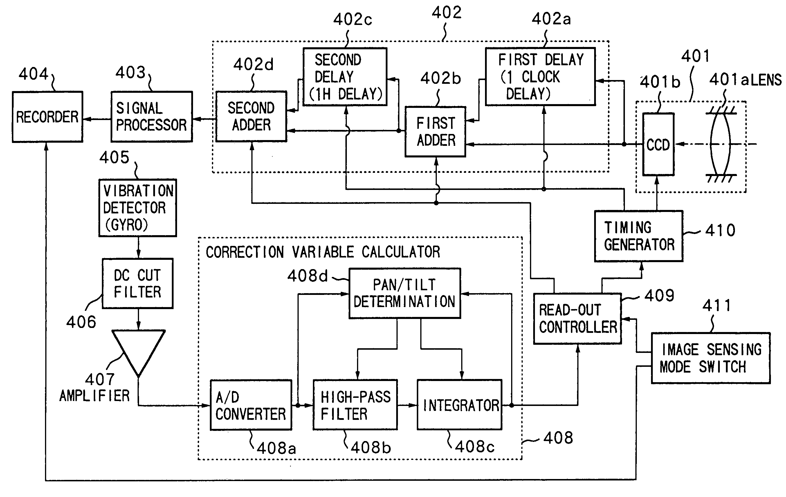
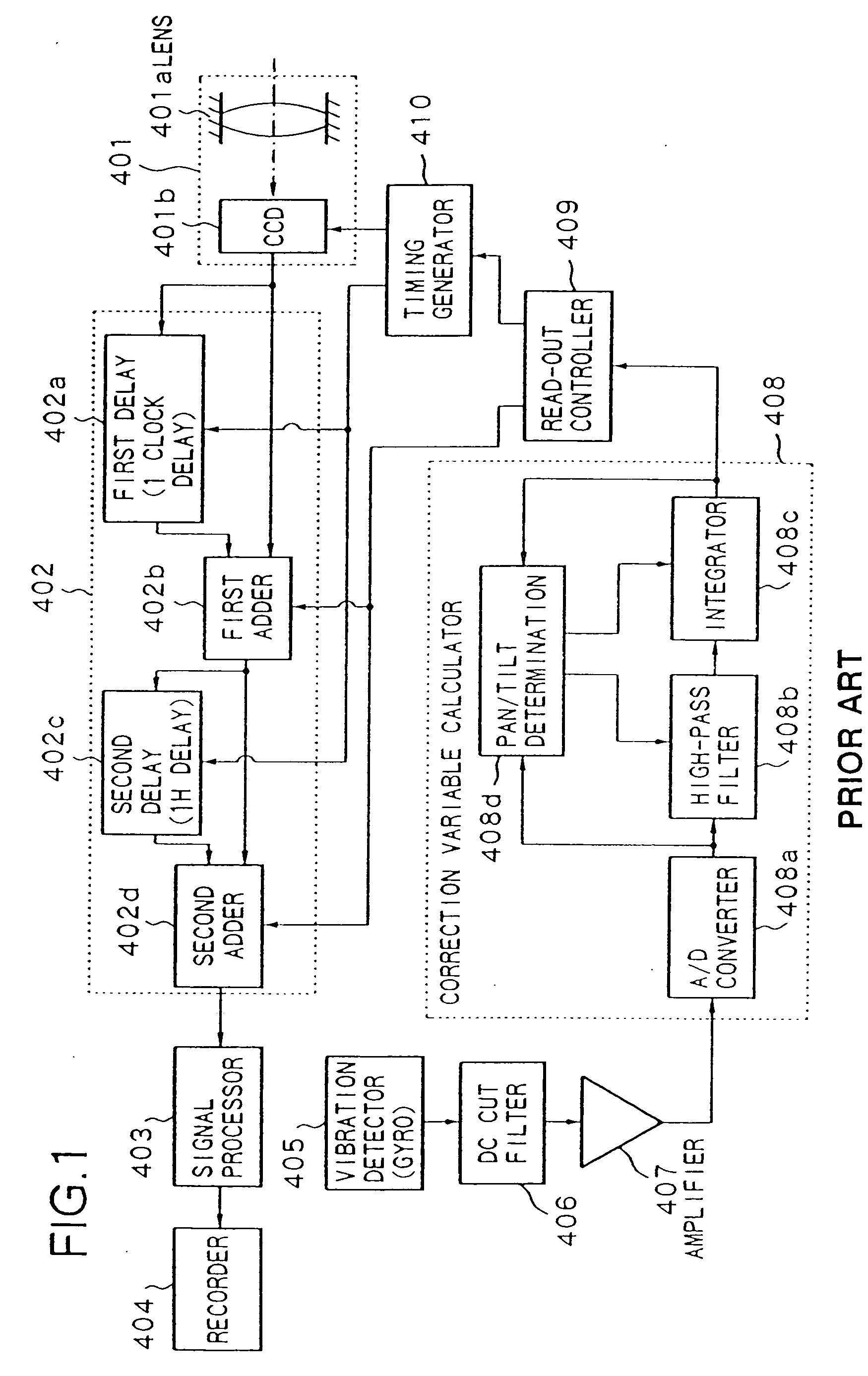
[0117] Next, a modified example of the first embodiment will be described with reference to FIG. 13. FIG. 13 is a block diagram showing a construction of an image sensing apparatus according to a modified example to the first embodiment which will be described later. Components shown in FIG. 13, which are identical to that of the aforementioned conventional example in FIG. 1 and that of the first embodiment in FIG. 11, have the same reference numerals.

[0118]FIG. 13 differs from FIG. 11 by having a first switch 301 and a second switch 302 in addition to the construction shown in FIG. 11. The first switch 301 and the second switch 302 select a-a′ or b-b′ in accordance with the switching mode of the image sensing mode switch 411, wherein a-a′ is a route in which image signals flow from the image sensing device 401b to the first adder 402b, then through the second delay 402c and second adder 402d to the signal processor 403, while b-b′ is a route in ...

second embodiment

[0122]FIG. 14 is a block diagram showing a construction of an image sensing apparatus (video camera) according to the second embodiment of the present invention. In FIG. 14, reference numeral 101 denotes lenses; 102, an image sensing device such as a CCD or the like; 103, an amplifier; 104, a camera signal processor; 105, an enlargement / interpolation / pixel shifting circuit for performing enlargement process, interpolation process, and pixel shifting process on image data; 106, a CCD driver; 107, a pitch angular velocity sensor; 108; a yaw angular velocity sensor; 109 and 110, amplifiers; 111, an anti-vibration control microcomputer; and 112, a switch. Note that the pitch angle sensor 107 and the yaw angle sensor 108 of the second embodiment correspond to the vibration detector 405 of the first embodiment, and the anti-vibration control microcomputer 111 of the second embodiment correspond to the correction variable calculator 408 of the first embodiment.

[0123] An enlargement or mag...


PUM


Abstract

A correction variable is calculated based on vibration data of an image sensing apparatus. Based on the calculation result, timing of reading image signals from an image sensing device is controlled. The read image signals are delayed by predetermined time, the read image signals and the delayed image signals are added at a predetermined addition ratio based on the calculation result of the correction variable calculator. In still image sensing, the above addition operation is not performed.

Description

BACKGROUND OF THE INVENTION [0001] The present invention relates to an image sensing apparatus comprising an electronic anti-vibration system which performs vibration correction by electrically extracting a sensed image based on vibration data of the image sensing apparatus main body. Particularly, the present invention relates to an image sensing method and apparatus capable of sensing a moving image and a still image, and a storage medium storing control programs for controlling the image sensing apparatus. [0002] Conventional image sensing apparatuses such as a video camera or the like have achieved automatic functions and multi-functions in various aspects, e.g., automatic exposure (AE), automatic focus (AF) and so forth. By virtue of this, high quality image sensing is possible. [0003] Furthermore, as the sizes of image sensing apparatuses become smaller and magnifications of optical systems become higher, vibration of the image sensing apparatus causes deteriorated sensed imag...

Claims


Application Information

Patent Timeline
Patent Type & Authority Applications(United States)
IPC IPC(8): H04N5/225H04N5/228H04N5/232
CPCH04N5/23245H04N5/23248H04N5/23274H04N5/23261H04N5/23258H04N23/6815H04N23/6842H04N23/68H04N23/6812H04N23/667
Inventor KAWAHARA, HIDEOYASUDA, HITOSHI
Owner CANON KK
Why Eureka
Try Eureka