Optical pick-up for optical disc device

Inactive Publication Date: 2005-07-21
HOYA CORP
View PDF14 Cites 20 Cited by
  • Summary
  • Abstract
  • Description
  • Claims
  • Application Information

AI Technical Summary

Benefits of technology

[0008] It seems that the objective lens disclosed in the document 1 is configured to suppress deterioration of optical performance due to tracking operation for the optical disc having lower re

Problems solved by technology

Therefore, the objective lens can not be used for the new standard optical disc.
If the laser beam of the blue laser diode is incident on the objective lens, various types of aberrations including the spherical a

Method used


Image

  • Optical pick-up for optical disc device
  • Optical pick-up for optical disc device
  • Optical pick-up for optical disc device

Examples


first example

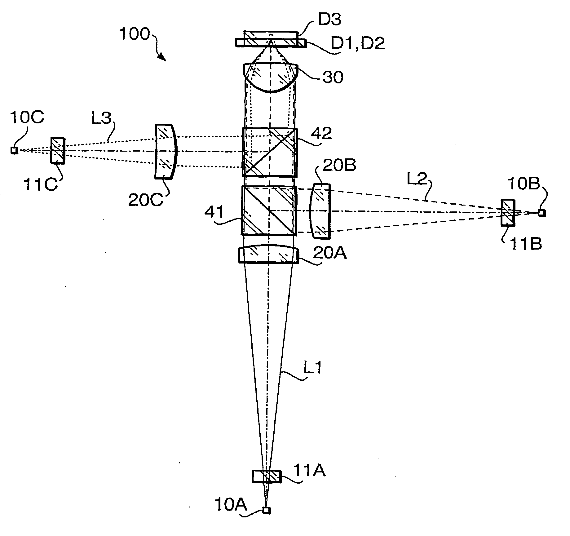
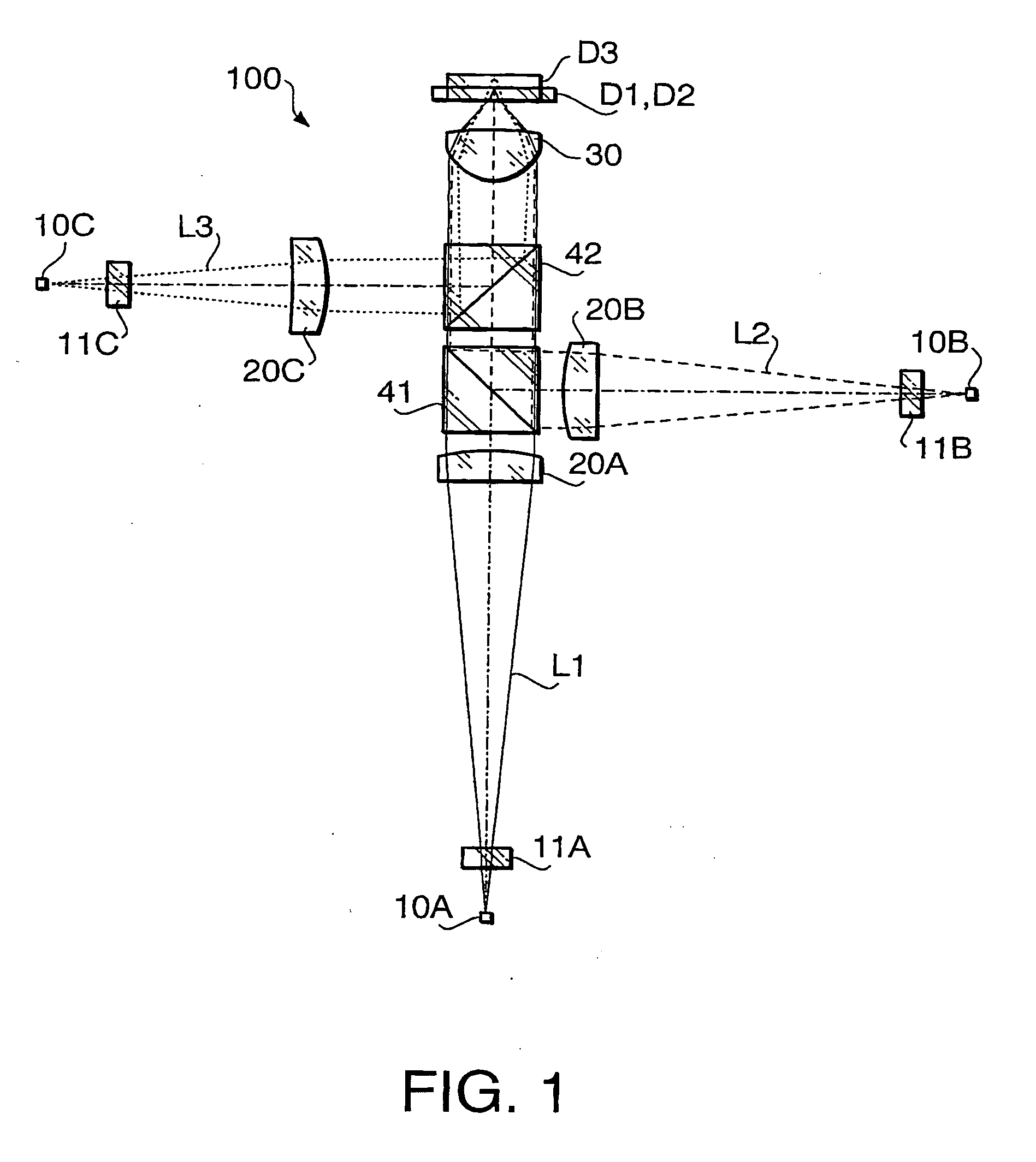
[0092] An optical pick-up according to a first example will be described. Since an objective lens according to the first example is not provided with the diffracting structure, the reference number 30 is used for the explanation about the objective lens 30 according to the first example. Specifications of the objective lens according to the first example are shown in Table 1.

TABLE 1laser beam L1laser beam L2laser beam L3Design wavelength405657788(nm)f3.0003.1003.118Focal length (mm)NA0.6500.6020.472magnification0.012−0.010−0.067

[0093] In Table 1, the design wavelength is a wavelength suitable for the recordation / reproduction of each optical disc, f represents a focal length (unit: mm) of the objective lens 30, NA represents the numerical aperture on an image side. In Table 1, the specifications are indicated with regard to each of the laser beams L1 to L3.

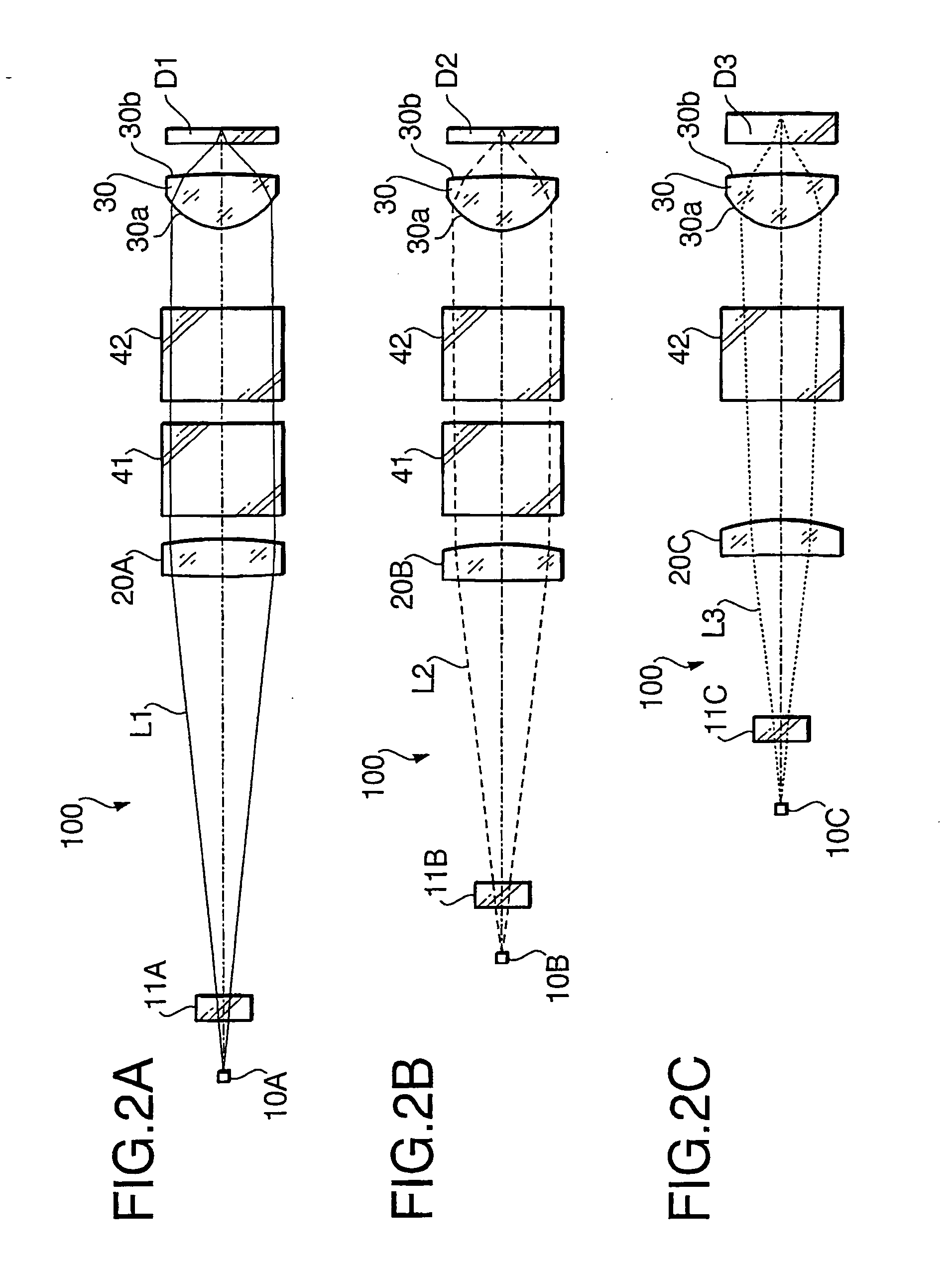
[0094] The laser beam L1 is incident on the objective lens 30 as a converging beam when the optical disc D1 is used. Each of t...

second example

[0107] Hereafter, an optical pick-up according to a second example will be described. Since an objective lens according to the second example is provided with the diffracting structure, the configuration of the objective lens according to the second example is explained with reference to FIG. 3. The reference number 300 is used for the explanation about the objective lens according to the second example. Since specifications and the numerical configuration of the optical pick-up 100 and the objective lens 300 according to the second example are the same as those of the first example shown in Tables 1 to 7, explanations thereof will not be repeated.

[0108] In the second example, the size of the diameter of the laser beam L1 on the surface 300a of the objective lens 300 is larger than that of the laser beam L2. For this reason, the surface 300a is provided with the diffracting structure so that a desirable NA is attained for each of the optical discs D1 to D3 and, each of the laser be...

third example

[0115] Hereafter, an optical pick-up according to a third example will be described. Since an objective lens according to the third example is provided with the diffracting structure, the configuration of the objective lens according to the third example is explained with reference to FIG. 3. The reference number 300 is used for the explanation about the objective lens according to the third example. Since specifications and the numerical configuration of the optical pick-up 100 and the objective lens 300 according to the third example are the same as those of the first example shown in Tables 1 to 7, explanations thereof will not be repeated.

[0116] Similarly to the second example, the surface 300a of the objective lens 300 is provided with first and third regions 31 to 33 so that the desirable NA is attained for each of the optical discs D1 to D3, and each of the laser beams L1 to L3 is suitably converged on the recording surface of the corresponding optical disc. However, the dif...


PUM


Abstract

There is provided an optical pick-up used for recording data to and/or reproducing data from at least three types of optical discs having at least two different thicknesses of cover layers. The optical pick-up includes light sources and an objective lens. A thickness t1 of a first optical disc, a thickness t2 of a second optical disc, and a thickness t3 of a third optical disc satisfy a relationship t1≦t2<t3. A numerical aperture NA1 for the first optical disc, a numerical aperture NA2 for the second optical disc and a numerical aperture NA3 for the third optical disc satisfy a relationship NA1≧NA2>NA3. Further, a first light beam for the first optical disc is incident on the objective lens as a converging light beam, and the second and third light beams for the second and third optical discs are incident on the objective lens as diverging light beams, respectively. Given that magnification of the objective lens is m1 when the first optical disc is used, magnification of the objective lens is m2 when the second optical disc is used, and magnification of the objective lens is m3 when the first optical disc is used, following conditions are satisfied: m1>0, m3<m2<0.

Description

BACKGROUND OF THE INVENTION [0001] The present invention relates to an optical pick-up and an objective lens used for an optical disc device, which is capable of recording data to and / or reproducing data from a plurality of types of optical discs having different recording densities and / or having different thicknesses of cover layers. [0002] There are various types of optical discs on which digital information is recorded at various densities, respectively. For example, a DVD (digital versatile disc) has a recording density higher that that of a CD (compact disc) or a CD-R (CD Recordable) and has a cover layer thinner than that of the CD or CD-R. [0003] When a recording / reproducing operation for the DVD having a higher recording density is performed, a smaller beam spot diameter is required on a recording surface of the DVD relative to a beam spot used for the CD having a lower recording density. For this reason, the optical pick-up is configured such that a NA (numerical aperture) ...

Claims


Application Information

Patent Timeline
IPC IPC(8): G02B13/00G02B13/18G11B7/00G11B7/125G11B7/1275G11B7/135G11B7/1353G11B7/1374
CPCG11B7/1275G11B2007/0006G11B7/1374G11B7/1353
Inventor KOREEDA, DALSUKEMARUYAMA, KOICHI
Owner HOYA CORP
Why Eureka
Try Eureka