Optical transmission system with automatic signal level adjustment and startup functions

Active Publication Date: 2005-07-21
FUJITSU LTD
View PDF7 Cites 43 Cited by
  • Summary
  • Abstract
  • Description
  • Claims
  • Application Information

AI Technical Summary

Benefits of technology

[0021] In view of the foregoing, it is an object of the present invention to provide an optical transmission system with automatic startup functions that optimize the power leve

Problems solved by technology

This fact means the following problems: First, such tasks are not error free.
Second, they need knowledge and skills.
Third, they are quite time-consuming since adjustment should take place at each individual node.
Although the workload of attenuator adjustment can be reduced by the use of such remote control facilities, service engineers are still burdened with some amount of manual tasks that the

Method used


Image

  • Optical transmission system with automatic signal level adjustment and startup functions
  • Optical transmission system with automatic signal level adjustment and startup functions
  • Optical transmission system with automatic signal level adjustment and startup functions

Examples


first embodiment

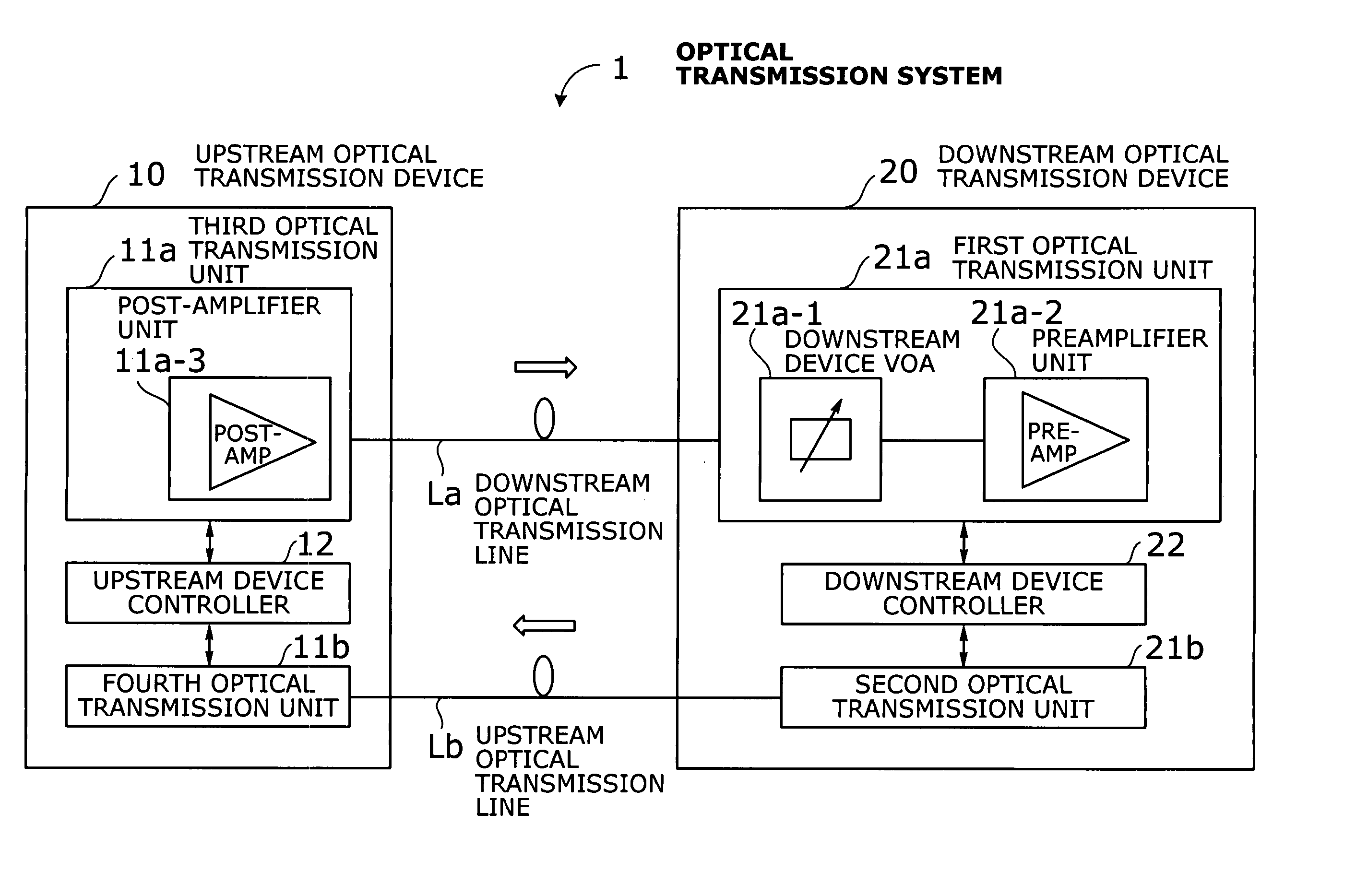
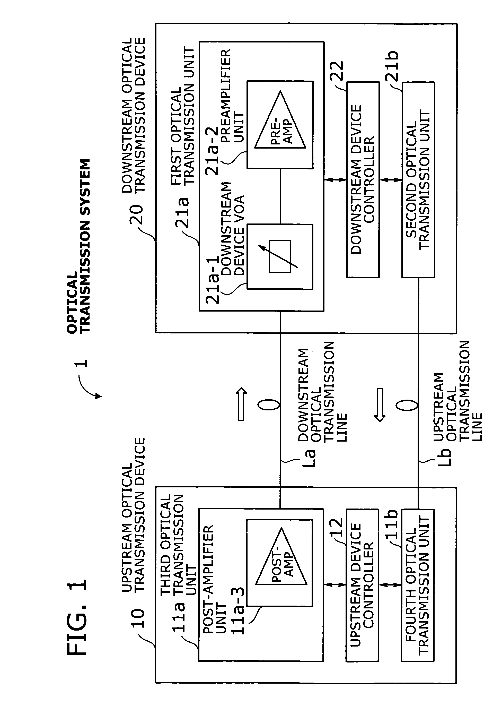
[0045] This section describes a more specific structure of the optical transmission system 1 according to the present invention. The following explanation, however, assumes a system with an intermediate repeater device, which is not shown in the simplified system of FIG. 1.

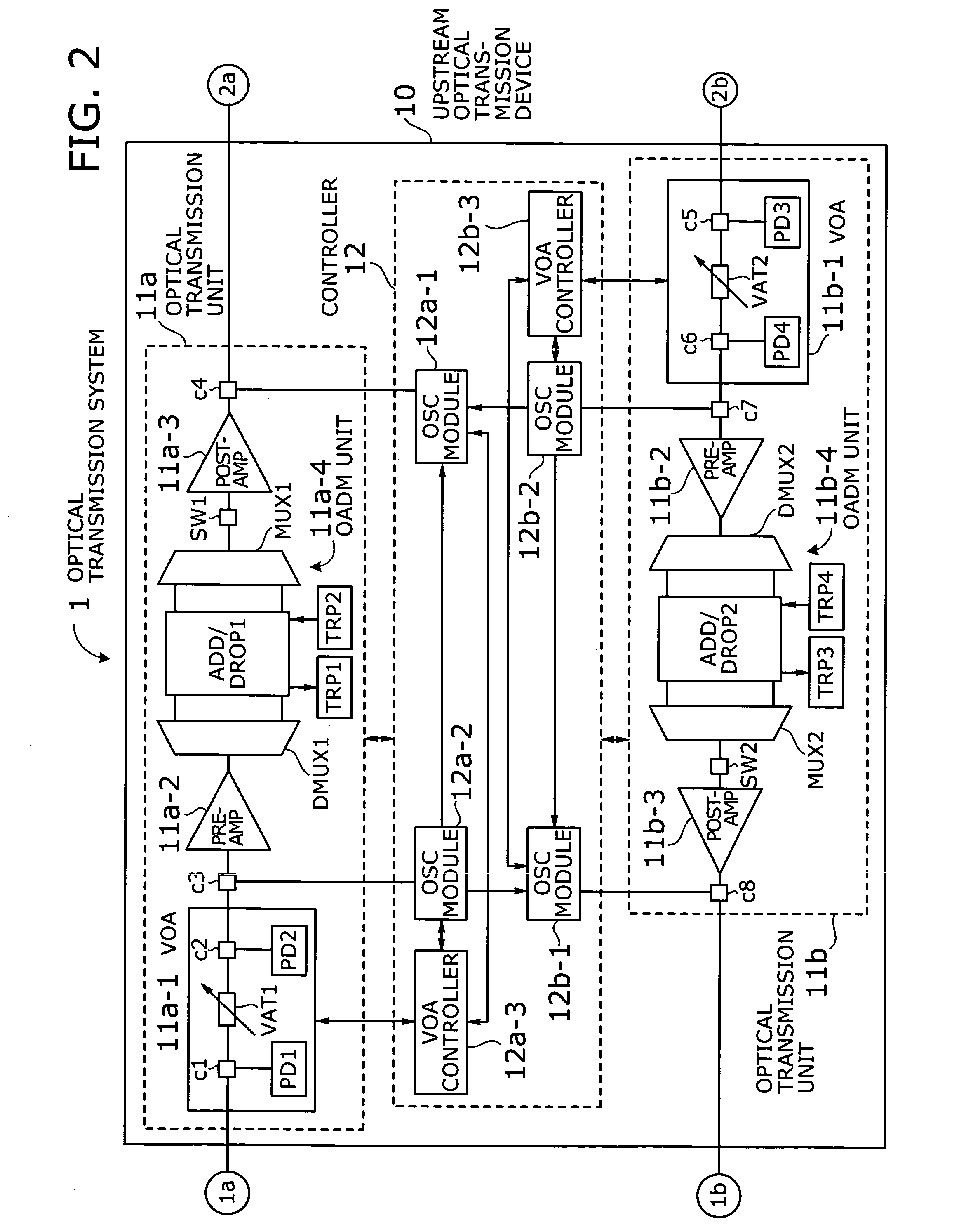
[0046] FIGS. 2 to 4 show the structure of an optical transmission system 1 according to a first embodiment of the present invention. Specifically, FIG. 2 shows an upstream optical transmission device 10 (referred to as “transmission device 10” where appropriate). FIG. 3 shows an intermediate optical transmission device 30 (referred to as “repeater device 30” where appropriate). FIG. 4 shows a downstream optical transmission device 20 (referred to as “transmission device 20” where appropriate).

[0047] Note that the terms “upstream” and “downstream” are used in a relative sense; that is, those labels of optical transmission devices depend on their relative locations. Think of, for example, two devices illustrated i...

second embodiment

[0108] In this section, we will describe an automatic startup process according to a second embodiment of the present invention, in which a VOA is attached to the output stage of each optical amplifier. FIGS. 9 to 11 show the structure of an optical transmission system 2 according to the second embodiment. Specifically, FIG. 9 is a block diagram of an upstream optical transmission device 40 (referred to as “transmission device 40” where appropriate). FIG. 10 is a block diagram of an intermediate optical transmission device 60 (referred to as “repeater device 60” where appropriate). FIG. 11 is a block diagram of a downstream optical transmission device 50 (referred to as “transmission device 50” where appropriate).

[0109] Unlike the first embodiment, the optical transmission system 2 employs a VOA at the output stage of (as opposed to at the front end of) each post-amplifier, inline amplifier, and preamplifier. In addition, the automatic startup process of this system 2 is designed n...

third embodiment

[0161] This section describes a system with automatic startup functions according to a third embodiment of the present invention. The third embodiment differs from the preceding two embodiments in that the transmission line loss of each section between nodes is calculated for use in startup processing that follows. The system of the third embodiment has the same structure as what we have described in FIGS. 2 to 4, except that the optical switch placed before every post-amplifier can be eliminated.

[0162]FIG. 17 is a flowchart of an automatic startup process according to the third embodiment of the invention. This process goes as follows:

[0163] (S71a) A service engineer inserts a preamplifier unit 21a-2 to the transmission device 20. This event triggers the controller 22 to begin startup processing. Note that OSC signals have to be available at this stage.

[0164] (S71b) The controller 22 examines whether OSC signals and main signals are available on the receiving transmission line. ...


PUM


Abstract

An optical transmission system with automatic startup functions to optimize the power level of optical signals entering each optical amplifier and operate those amplifiers in appropriate mode. In the process of starting up an optical transmission system, upstream and downstream optical transmission devices set up themselves under the coordination of their internal controllers. The downstream device controller adjusts its local variable optical attenuator by utilizing optical noise emission from a post-amplifier in the upstream optical transmission device, and it selects and sets a preamplifier unit to work in appropriate operating mode. The upstream device controller, on the other hand, selects and sets operating mode of its local post-amplifier unit. During this process, the upstream and downstream device controllers exchange messages over supervisory control channels to achieve the purpose.

Description

CROSS-REFERENCE TO RELATED APPLICATIONS [0001] This application is based upon and claims the benefits of priority from the prior Japanese Patent Application No. 2004-007857, filed on Jan. 15, 2004, the entire contents of which are incorporated herein by reference. BACKGROUND OF THE INVENTION [0002] 1. Field of the Invention [0003] The present invention relates to an optical transmission system, and more particularly to an optical transmission system which transports optical signals using wavelength-division multiplexing techniques. [0004] 2. Description of the Related Art [0005] Wavelength-division multiplexing (WDM) techniques are widely used in today's optical communications infrastructures. A WDM system carries many transmission signals (e.g., forty to one hundred waves) over a single fiber-optic medium, with different optical wavelengths assigned to different channels. Long-haul WDM systems employ a number of optical amplifiers to boost optical signals. They include: preamplifie...

Claims


Application Information

Patent Timeline
IPC IPC(8): H04B10/07H04B10/077H04B10/079H04B10/293H04B10/296H04B10/297H04B10/564H04B10/572H04J14/00H04J14/02
CPCH04B10/0775H04B2210/078H04B10/2933
Inventor TOMOFUJI, HIROAKIMAEDA, TAKUJIMAEDA, TAIZOKOBAYASHI, HIDEKINAGAYOSHI, TATSUOWADA, TETSUO
Owner FUJITSU LTD
Why Eureka
Try Eureka