
Semiconductor devices

a technology of semiconductor devices and semiconductors, applied in semiconductor devices, capacitors, electrical devices, etc., can solve the problems of increasing device cost, complex process, and easy damage to the structure of fig. 6 and other problems, to achieve the effect of reducing the associated problems

Inactive Publication Date: 2005-07-21
ROUND ROCK RES LLC
View PDF99 Cites 95 Cited by
  • Summary
  • Abstract
  • Description
  • Claims
  • Application Information

AI Technical Summary

Benefits of technology

"The present invention provides a new method that reduces problems associated with the manufacture of semiconductor devices, particularly problems resulting from instability of unsupported capacitor bottom plates prior to formation of a supporting layer. Additionally, the invention provides lateral support for a vertically-oriented structure, such as a storage capacitor. These technical effects will be useful for those working in the field of semiconductor device manufacturing."

Problems solved by technology

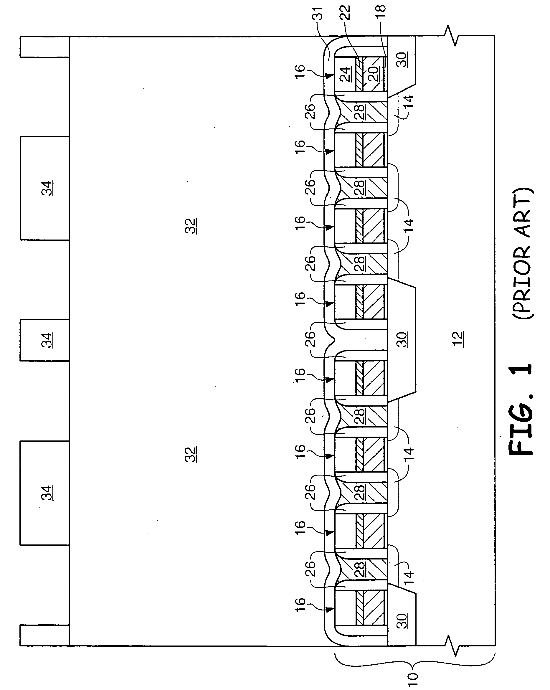
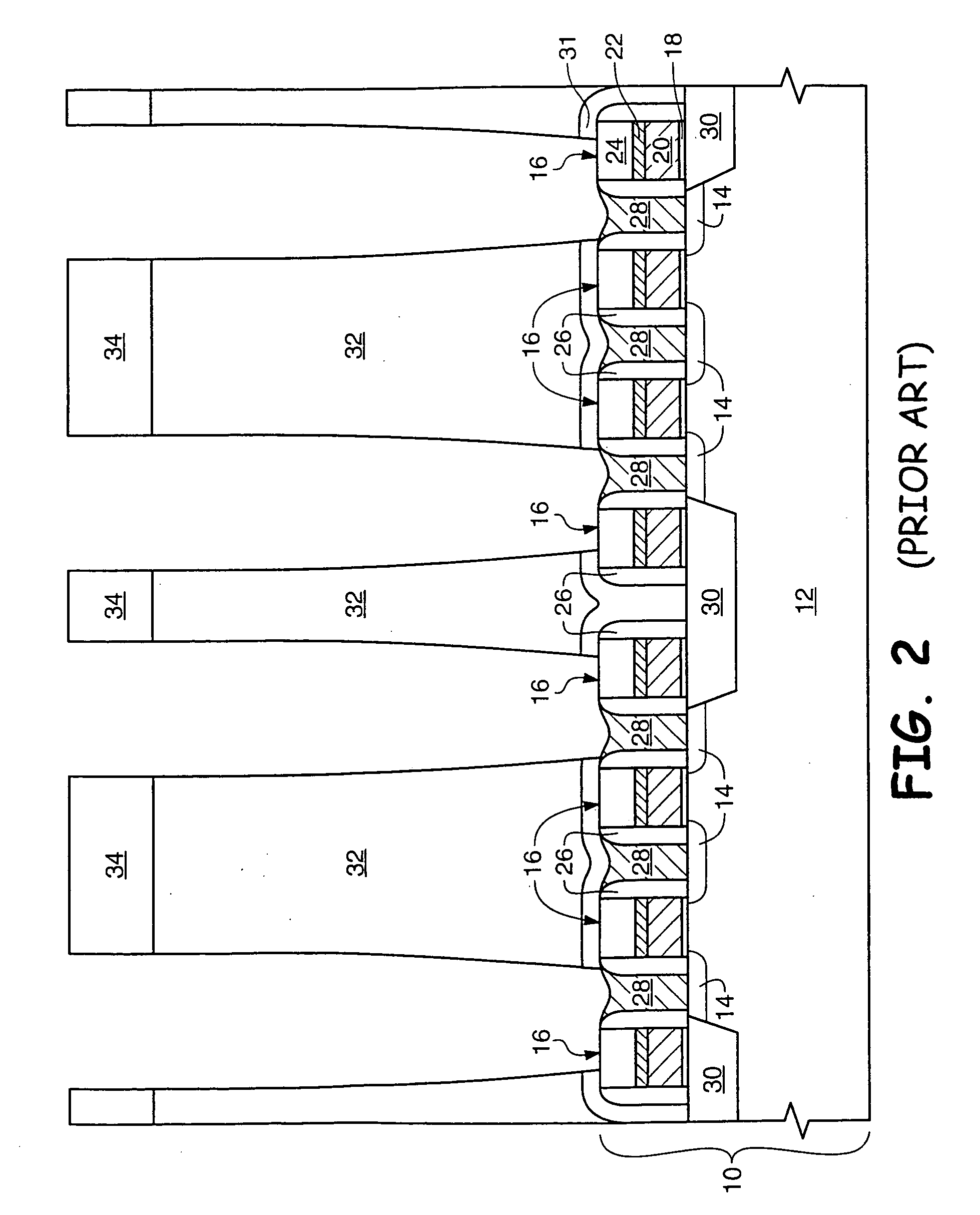
The structure of FIG. 6 is easily damaged and susceptible to defects such as leaning (caused, for example, during the etch of BPSG 32 of FIG. 5 to result in FIG. 6), toppling, or lifting of the bottom plate.
Such a process is complex and adds significantly to device cost.
Another problem which can occur during conventional processing results indirectly from the etch of BPSG layer 32 of FIG. 5 to result in the FIG. 6 structure.
The requirement to backfill and planarize results in additional processing steps, which contributes to a further increase in costs.

Method used


Image

  • Semiconductor devices
  • Semiconductor devices
  • Semiconductor devices

Examples


Embodiment Construction

[0020] The term “wafer” is to be understood as a semiconductor-based material including silicon, silicon-on-insulator (SOI) or silicon-on-sapphire (SOS) technology, doped and undoped semiconductors, epitaxial layers of silicon supported by a base semiconductor foundation, and other semiconductor structures. Furthermore, when reference is made to a “wafer” in the following description, previous process steps may have been utilized to form regions or junctions in or over the base semiconductor structure or foundation. Additionally, when reference is made to a “substrate assembly” in the following description, the substrate assembly may include a wafer with layers including dielectrics and conductors, and features such as transistors, formed thereover, depending on the particular stage of processing. In addition, the semiconductor need not be silicon-based, but could be based on silicon-germanium, silicon-on-insulator, silicon-on-sapphire, germanium, or gallium arsenide, among others. ...


PUM


Abstract

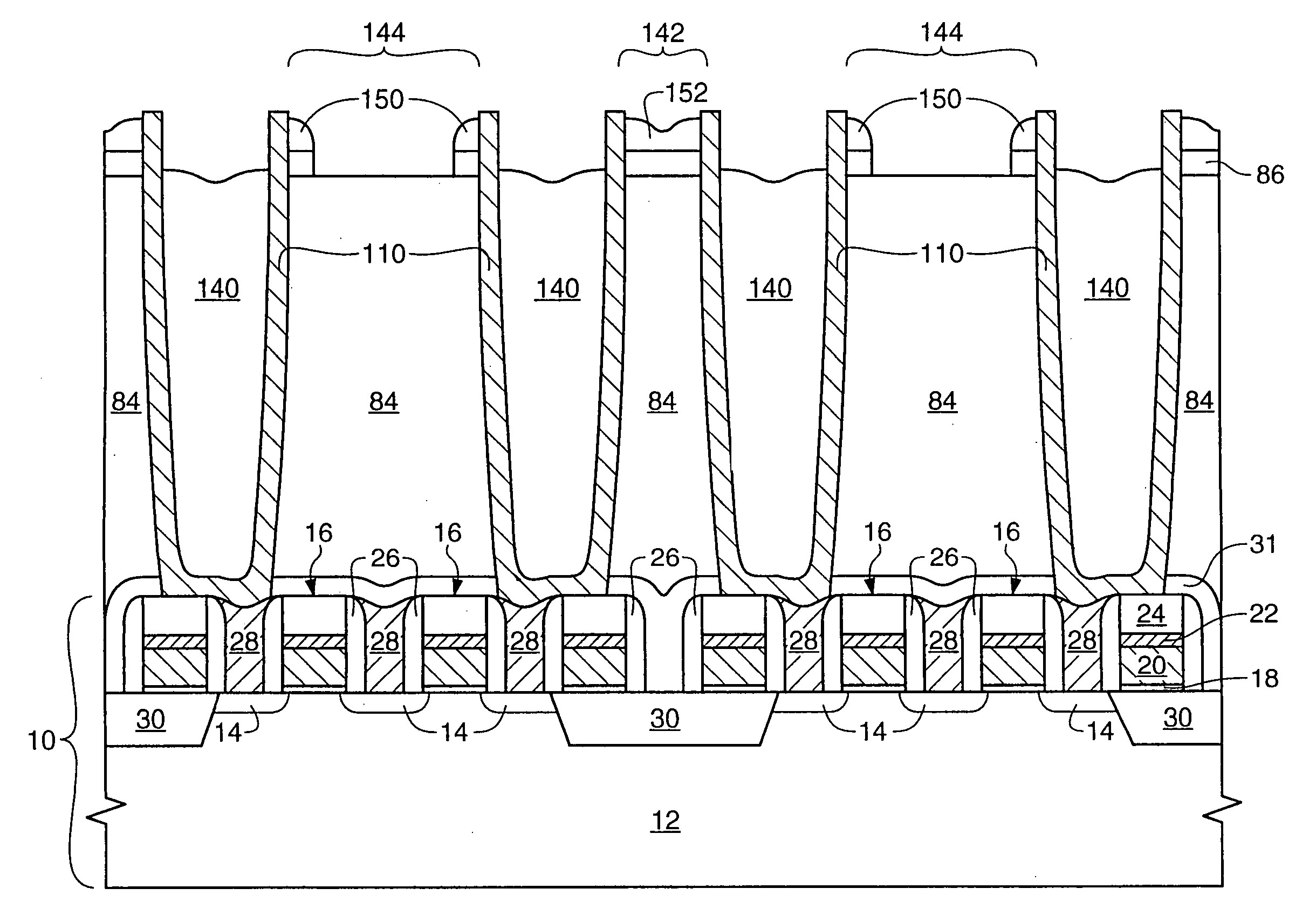
A method for forming double-sided capacitors for a semiconductor device includes forming a dielectric structure which supports capacitor bottom plates during wafer processing. The structure is particularly useful for supporting the bottom plates during removal of a base dielectric layer to expose the outside of the bottom plates to form a double-sided capacitor. The support structure further supports the bottom plates during formation of a cell dielectric layer, a capacitor top plate, and final supporting dielectric. An inventive structure is also described.

Description

FIELD OF THE INVENTION [0001] This invention relates to the field of semiconductor manufacture and, more particularly, to a method for forming a double-sided capacitor having lateral support for its capacitor bottom plate. BACKGROUND OF THE INVENTION [0002] During the manufacture of semiconductor devices which comprise memory elements, such as dynamic random access memories (DRAMs), static random access memories (SRAMs), and some microprocessors, capacitors such as container capacitors and pedestal capacitors are commonly formed. Container and pedestal capacitors are well known to allow an increased stored charge over planar capacitors by increasing the surface area on which the charge may be stored. [0003]FIGS. 1-7 depict a conventional method for forming a plurality of container capacitors from polysilicon. Formation of a pedestal capacitor is similar, but the bottom plate is a solid plug and the cell dielectric and top plate are conformal with the exterior of the bottom plate to ...

Claims


Application Information

Patent Timeline
Patent Type & Authority Applications(United States)
IPC IPC(8): H01L21/02H10B12/00
CPCH01L27/10817H01L28/91H01L27/10894H01L27/10852H10B12/318H10B12/09H10B12/033H10B99/00
Inventor MANNING, HOMER M.
Owner ROUND ROCK RES LLC
Learn More