
PCMO spin-coat deposition

a technology of pcmo and spin-coat, which is applied in the direction of chemistry apparatus and processes, instruments, and semiconductor/solid-state device details, etc., can solve the problems of reducing reducing the leakage current, and voids that are extremely detrimental to the performance of rram devices

Inactive Publication Date: 2005-07-21
XENOGENIC DEV LLC
View PDF2 Cites 14 Cited by
  • Summary
  • Abstract
  • Description
  • Claims
  • Application Information

AI Technical Summary

Benefits of technology

"The present invention describes a new process for spin-coating PCMO onto a noble metal substrate that eliminates the formation of voids at the bottom of both trenches and vias. This is achieved by using a two-step process where a substrate is first spin-coated with acetic acid and then with a low concentration of PCMO solution, followed by a second concentration of PCMO solution with a greater concentration of PCMO. Baking and rapid thermal annealing (RTA) are then repeated one to five times before post-annealing. This process results in a void-free PCMO film with a void-free interface between the PCMO film and the underlying substrate surface."

Problems solved by technology

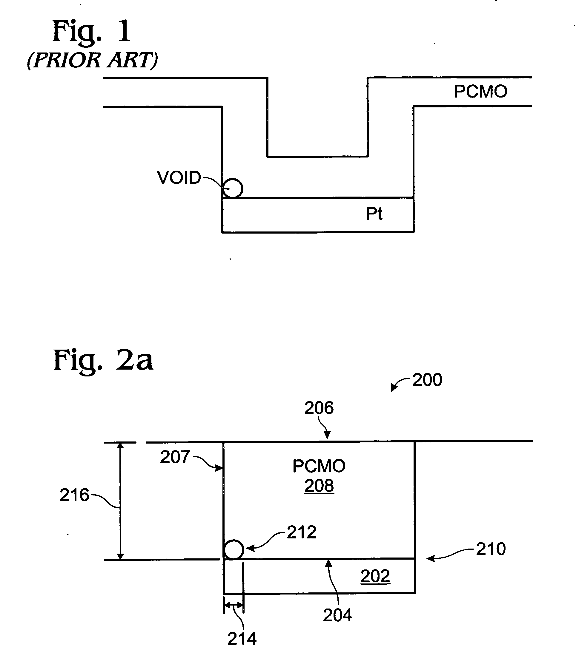
The problem is likely a result of the poor wetting properties of the PCMO spin-coating solution on the Pt surface.
These voids are extremely detrimental to performance of RRAM devices.
The voids encourage the formation of shorts between the top and bottom electrodes and degrade (increase) the leakage current.
Further, the voids may result in the PCMO film being peeled from the Pt substrate during subsequent fabrication processes, such as during a chemical mechanical polish (CMP) step.

Method used


Image

  • PCMO spin-coat deposition
  • PCMO spin-coat deposition
  • PCMO spin-coat deposition

Examples


Embodiment Construction

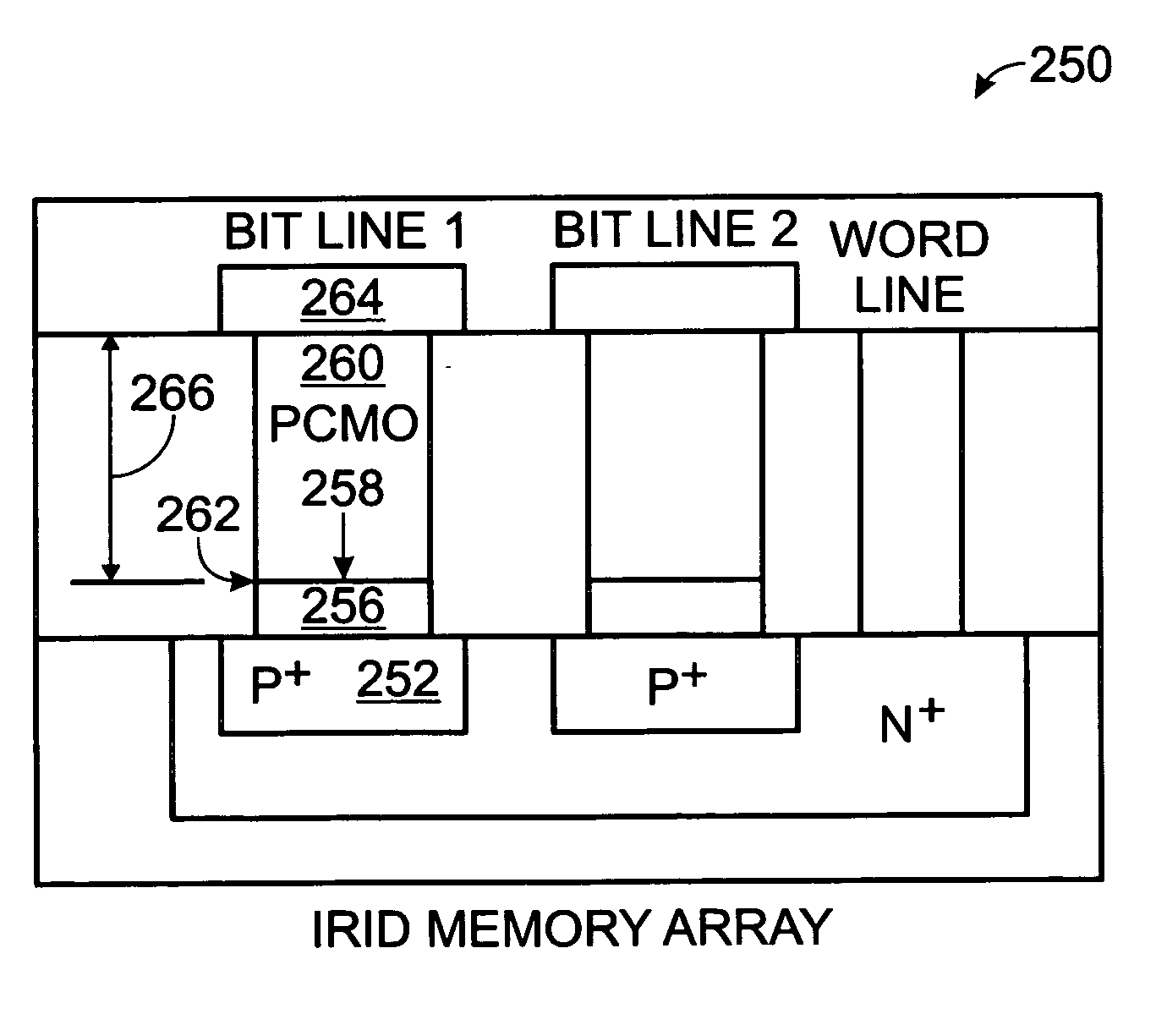
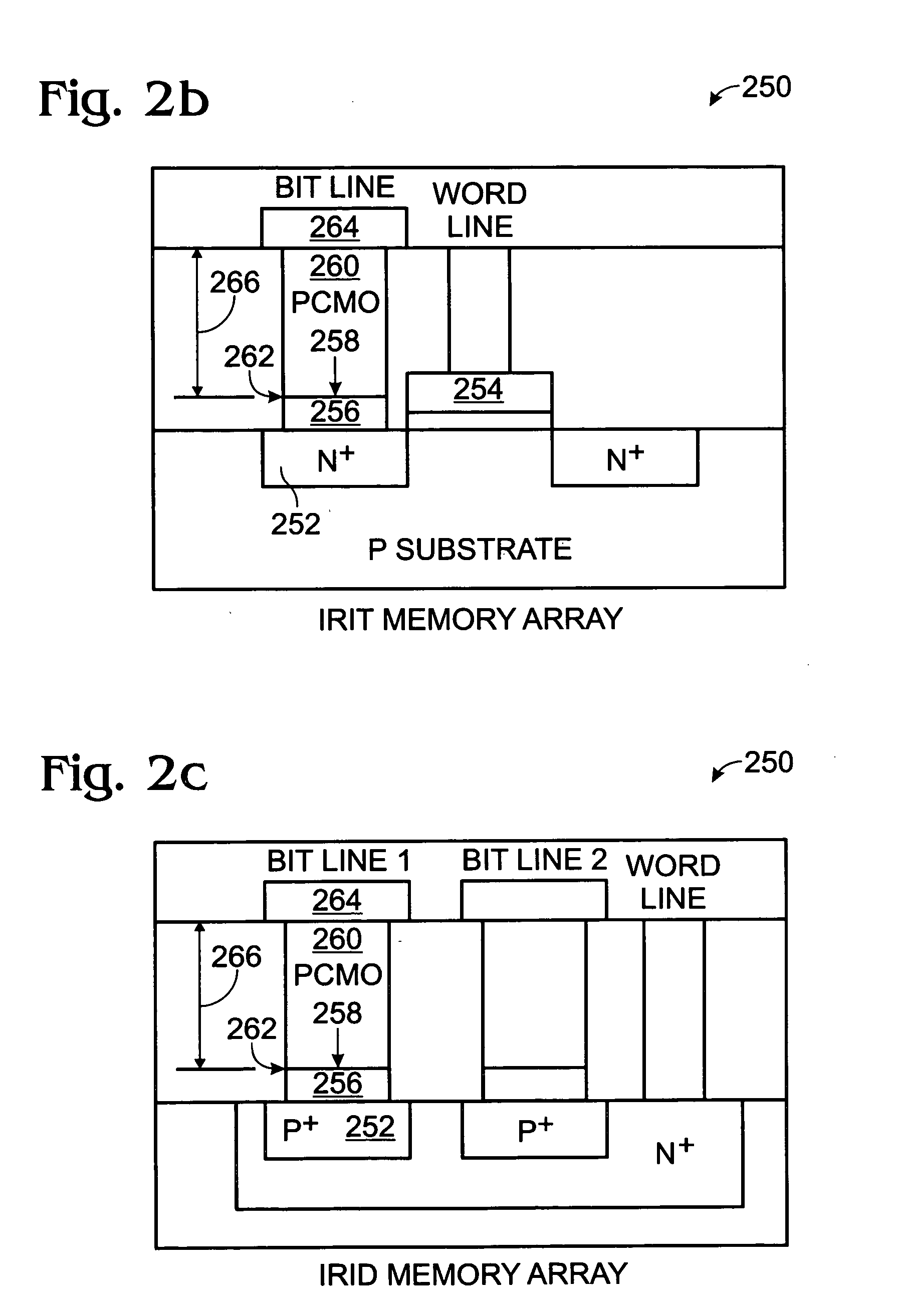
[0020]FIG. 2a is a partial cross-sectional view of the present invention void-free PCMO film structure. The structure 200 comprises a substrate 202, including a noble metal, with a surface 204. The substrate 202 can be a material such as Pt, Rh, Ir, Pt—Rh, Pt—Ir, or Ir—Rh. However, other noble metals, noble metal compounds, and even other metals besides noble metals can be used in other aspects of the invention. A feature 206 is shown that is normal with respect to the substrate surface 204. Alternately stated, the feature 206, which can be either a via or a trench, has an element or structure, such as a sidewall 207, that is formed in a vertical plane perpendicular to the horizontal surface 204. Note, the feature 206 may also have an element or structure, such as a via or trench bottom surface formed in a plane that is parallel to the surface 204.

[0021] A PCMO film 208 overlies the substrate surface 204. The Pr1−XCaXMnO3 film 208 X variable may be in the range of 0.1 to 0.6. A voi...


PUM

PropertyMeasurementUnit
timeaaaaaaaaaa
timeaaaaaaaaaa
concentrationaaaaaaaaaa

Abstract

A Pr1-XCaXMnO3 (PCMO) spin-coat deposition method for eliminating voids is provided, along with a void-free PCMO film structure. The method comprises: forming a substrate, including a noble metal, with a surface; forming a feature, such as a via or trench, normal with respect to the substrate surface; spin-coating the substrate with acetic acid; spin-coating the substrate with a first, low concentration of PCMO solution; spin-coating the substrate with a second concentration of PCMO solution, having a greater concentration of PCMO than the first concentration; baking and RTA annealing (repeated one to five times); post-annealing; and, forming a PCMO film with a void-free interface between the PCMO film and the underlying substrate surface. The first concentration of PCMO solution has a PCMO concentration in the range of 0.01 to 0.1 moles (M). The second concentration of PCMO solution has a PCMO concentration in the range of 0.2 to 0.5 M.

Description

BACKGROUND OF THE INVENTION [0001] 1. Field of the Invention [0002] This invention generally relates to integrated circuit (IC) fabrication and, more particularly, to a PCMO deposition process that forms a void-free interface with an underlying noble metal substrate. [0003] 2. Description of the Related Art [0004] Pr1-XCaXMnO3 (PCMO) thin films have been found to have unique resistance change properties. With the application of a narrow nanosecond pulse, having an amplitude of 5 volts and a duration of 100 nanoseconds, the resistance can be changed to a high resistant state. Likewise, if a wider microsecond pulse is applied, the resistance can be reset to its initial (low-resistance) state. The observed change in resistance states is in the range of one to three orders of magnitude. Further, a resistance state changes can be affected in a PCMO film with the application of an opposite amplitude polarity narrow (nanosecond range) pulses. Thus, the resistance state of the PCMO film can...

Claims


Application Information

Patent Timeline
Patent Type & Authority Applications(United States)
IPC IPC(8): H01L21/28C01G45/00H01L23/62H01L27/10H01L27/24H01L45/00
CPCG11C13/0007G11C2213/31H01L27/2409H01L27/2436H01L45/1683H01L45/1233H01L45/147H01L45/1608H01L45/04H10B63/20H10B63/30H10N70/20H10N70/826H10N70/8836H10N70/021H10N70/066
Inventor ZHUANG, WEI-WEISTECKER, LISA H.STECKER, GREGORY M.HSU, SHENG TENG
Owner XENOGENIC DEV LLC
Learn More