Multi-catheter insertion device and method

a multi-catheter, catheter technology, applied in the direction of catheters, other medical devices, guide needles, etc., can solve the problems of obstruction or clogging, interfere with the perfusion of the nervous system, and obstruction of the system, so as to prevent or reduce the risk of clogging

Inactive Publication Date: 2005-07-21
INTEGRA LIFESCI SWITZERLAND SARL
View PDF30 Cites 30 Cited by
  • Summary
  • Abstract
  • Description
  • Claims
  • Application Information

AI Technical Summary

Benefits of technology

[0012] A variety of configurations are provided for mating the secondary catheters to the primary catheter. In one embodiment, for example, the secondary catheters each include a proximal end mated to the connecting end of the primary catheter, and a sealed distal end. In another embodiment, the connecting end of the primary catheter includes an end cap having several bores leading to the inner lumen of the primary catheter. Each bore is adapted to mate to or receive one of the secondary catheters. The end cap and the bores in the primary catheter are effective to form a seal between the fluid passageway formed in each of the secondary catheters and the inner lumen of the primary catheter. In another embodiment, the secondary catheters can be formed integrally with the primary catheter.
[0013] The shunt device can optionally include at least one support bracket disposed between each of-the-secondary catheters for securing the secondary catheters in a desired position relative to each other. For example, the support brackets can be adapted to position the secondary catheters at a predetermined distance apart from each other. This configuration is effective to prevent or reduce the risk of blockage of the fluid entry ports in the secondary catheters.
[0014] In others aspects, the shunt device can be adapted to receive a rigid stylet for implanting the shunt device at a treatment site. The connecting end of the primary catheter can include a self-sealing valve, e.g., a septum, adapted to receive a rigid stylet. The self-sealing valve is preferably disposed between the inner lumen of the primary catheter and a region external to the inner lumen of the primary catheter. Each support bracket can also include a central bore extending therethrough and adapted to receive the rigid stylet. In use, the rigid stylet is removably disposed through the inner lumen of the primary catheter, through the self-sealing valve in the connecting end of the primary catheter, between the plurality of secondary catheters, and through at least one of the support brackets. The shunt device can also optionally include a distal cap disposed around the distal end of each of the secondary catheters. The distal cap is effective to prevent a distal end of the rigid stylet from extending beyond the distal end of the device.

Problems solved by technology

This increasing pressure can interfere with the perfusion of the nervous system.
The most common complication with shunting is obstruction of the system.
Although obstruction or clogging may occur at any point along the shunt system, it most frequently occurs at the ventricular end of the shunt system.
While there are several ways that the ventricular catheter may become blocked or clogged, obstruction is typically caused by growth of tissue, such as the choroid plexus, around the catheter and into the pores.
The pores of the ventricular catheter can also be obstructed by debris, bacteria, or blood clogged in the pores of the catheter.
Additionally, problems with the ventricular catheter can arise from overdrainage of the CSF, which can cause the ventricle walls to collapse upon the catheter and block the pores in the catheter wall, thereby preventing CSF drainage.
This process can be ineffective, however, due to the small size of the pores of the ventricular catheter and due to the small amount of flushing liquid available in the shunt system.
As with the process of backflushing, using a built-in mechanism to flush the shunt system can also fail to remove the obstruction due to factors such as the size of the pores and the degree and extent to which the pores have been clogged.
These repairs, however, may be incapable of removing obstructions from the ventricular catheter depending on the location of the clogged pores.
Additionally, the extent of tissue growth into and around the catheter can also preclude the creation of additional pores, for example, in situations where the tissue growth covers a substantial portion of the ventricular catheter.
Another disadvantage of creating new apertures to repair an occluded ventricular catheter is that this method fails to prevent or reduce the risk of repeated obstructions.
Because attempts at flushing or repairing a blocked ventricular catheter are often futile and ineffective, occlusion is more often treated by replacing the catheter.
Although this can be accomplished by simply removing the obstructed catheter from the ventricle, the growth of the choroid plexus and other tissues around the catheter and into the pores can hinder removal and replacement of the catheter.
Not only do these procedures pose a significant risk of injury to the patient, they can also be very costly, especially when shunt obstruction is a recurring problem.

Method used


Image

  • Multi-catheter insertion device and method
  • Multi-catheter insertion device and method
  • Multi-catheter insertion device and method

Examples


Embodiment Construction

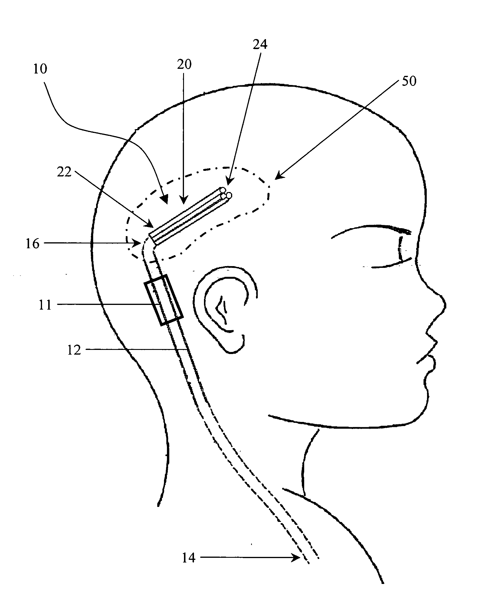
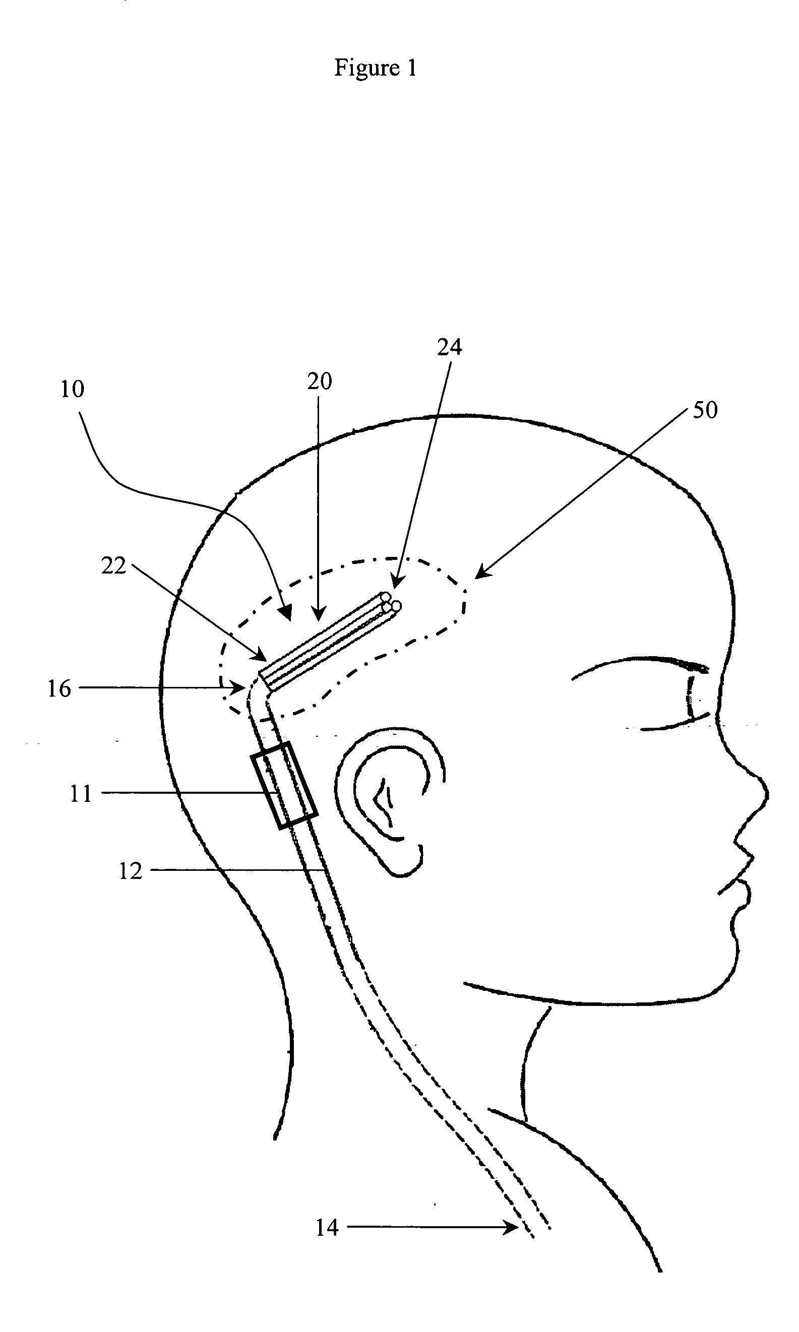
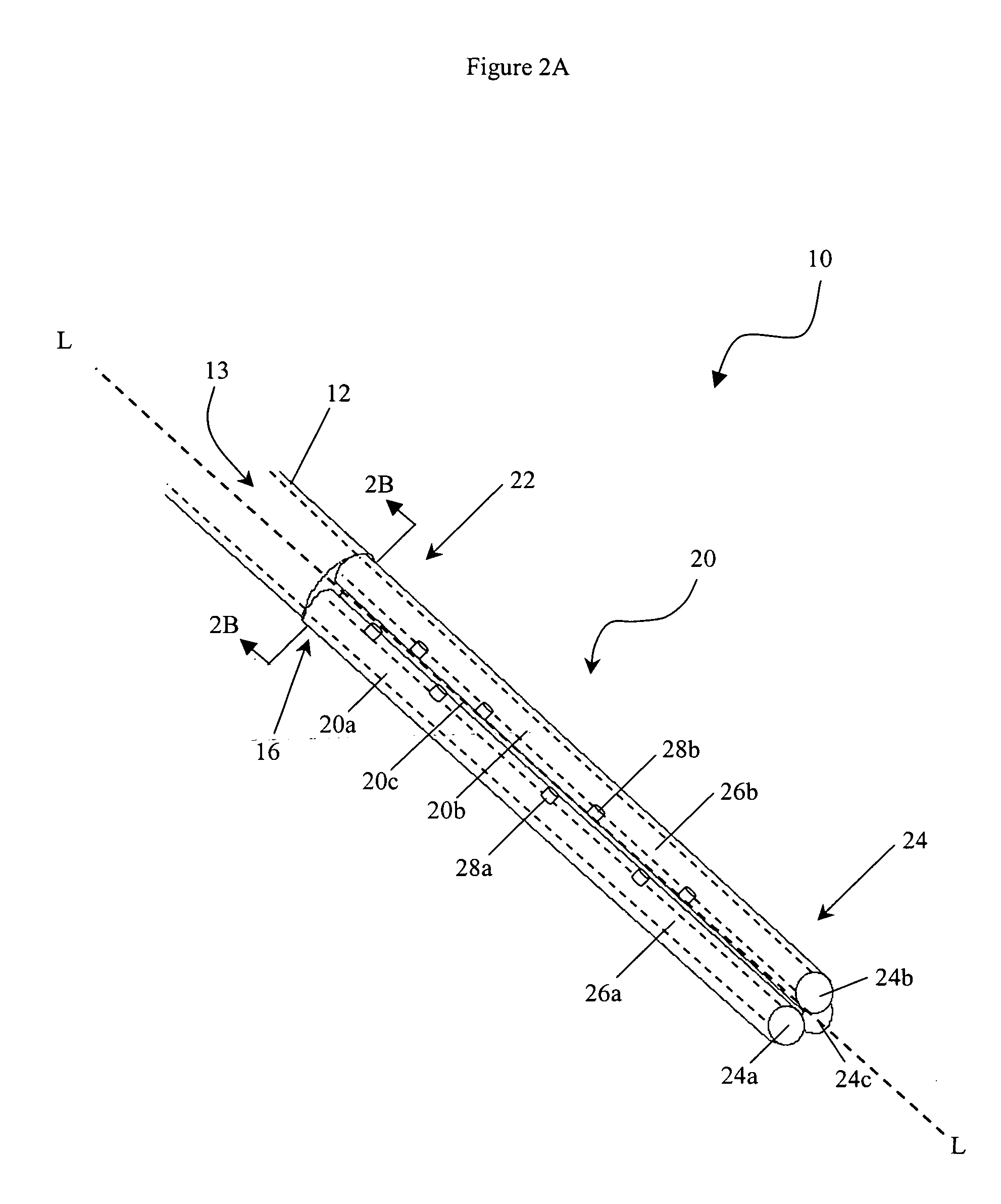
[0026] As shown in FIG. 1, the present invention generally provides an implantable shunt device 10 including a primary catheter 12, or trunk conduit, having a first, open end 14, and a second, connecting end 16, and at least two secondary catheters 20, or branch conduits, extending from the connecting end 16 of the primary catheter 12. For illustration purposes, only three secondary catheters 20a, 20b, 20c are shown. However, a person having ordinary skill in the art will appreciate that the shunt device 10 can include two or more secondary catheters 20.

[0027] The shunt device 10 can be used for a variety of diagnostic and therapeutic procedures, including for the removal or introduction of fluid to a treatment site. In an exemplary embodiment, as shown in FIG. 1, the shunt device is used for treating hydrocephalus. The secondary catheters 20, and optionally at least a portion of the primary catheter 12, are implanted within one of the patient's cerebral ventricles, which contains ...


PUM


Abstract

An implantable shunt device having a primary catheter and at least two secondary catheters extending from the primary catheter is provided. The primary catheter includes a connecting end, an open end, and an inner lumen extending therebetween. Each of the secondary catheters extend from the connecting end of the primary catheter and include a fluid passageway formed therein in fluid communication with the inner lumen of the primary catheter. Each secondary catheter also includes at least one fluid entry port in fluid communication with the fluid passageway. In an exemplary embodiment, the fluid entry ports are disposed on an inwardly facing portion of each of the secondary catheters. The shunt device can be used for a variety of diagnostic and therapeutic procedures, including for the removal or introduction of fluid to a treatment site.

Description

CROSS-REFERENCE TO RELATED APPLICATIONS [0001] This APPLICATION is a continuation of application Ser. No. 10 / 047,204, filed Jan. 14, 2002, which is hereby incorporated by reference in its entirety.FIELD OF THE INVENTION [0002] The present invention relates to a catheter device and method useful with a shunt system, and in particular to a multi-catheter shunt device that minimizes the risk of blockage or obstruction or the catheter pores. BACKGROUND OF THE INVENTION [0003] Hydrocephalus is a neurological condition that is caused by the abnormal accumulation of cerebrospinal fluid (CSF) within the ventricles, or cavities, of the brain. CSF is a clear, colorless fluid that is primarily produced by the choroid plexus and surrounds the brain and spinal cord. CSF constantly circulates through the ventricular system of the brain and is ultimately absorbed into the bloodstream. CSF aids in the protection of the brain and spinal cord. First, because CSF keeps the brain and spinal cord buoyan...

Claims


Application Information

Patent Timeline
Patent Type & Authority Applications(United States)
IPC IPC(8): A61M25/00A61M1/00A61M25/06A61M27/00
CPCA61M25/0662A61M27/002A61M2210/0693A61M2025/0042A61M2025/0681A61M27/006
Inventor DEXTRADEUR, ALAN J.MAGRAM, GARY
Owner INTEGRA LIFESCI SWITZERLAND SARL
Why Eureka
Try Eureka