Dynamic filter

Inactive Publication Date: 2005-07-21
OPTIMUM POWER TECH LP
View PDF10 Cites 4 Cited by
  • Summary
  • Abstract
  • Description
  • Claims
  • Application Information

AI Technical Summary

Benefits of technology

[0009] The present invention is directed to a dynamic filter that alters the amount of filtering provided dependent upon a magnitude of change occurring in a signal. The dynamic filter may be applied to an input signal received at a data acquisition unit or another value received by or determined by the data acquisition unit. The term “determined value” is meant to include any value, current or previous, raw or filtered, unprocessed or processed and may include, for example, sensed signals and values, and values determined otherwise such as by calculation by a data acquisition unit, an engine c

Problems solved by technology

In data acquisition systems, undesirable noise is often generated by a sensor or its wiring that skews the value read from the actually sensed value.
For example undesirable signal distortion can result from the vibration of mechanical sensors or from systems that operate unsteadily.
For exa

Method used


Image

  • Dynamic filter
  • Dynamic filter
  • Dynamic filter

Examples


Embodiment Construction

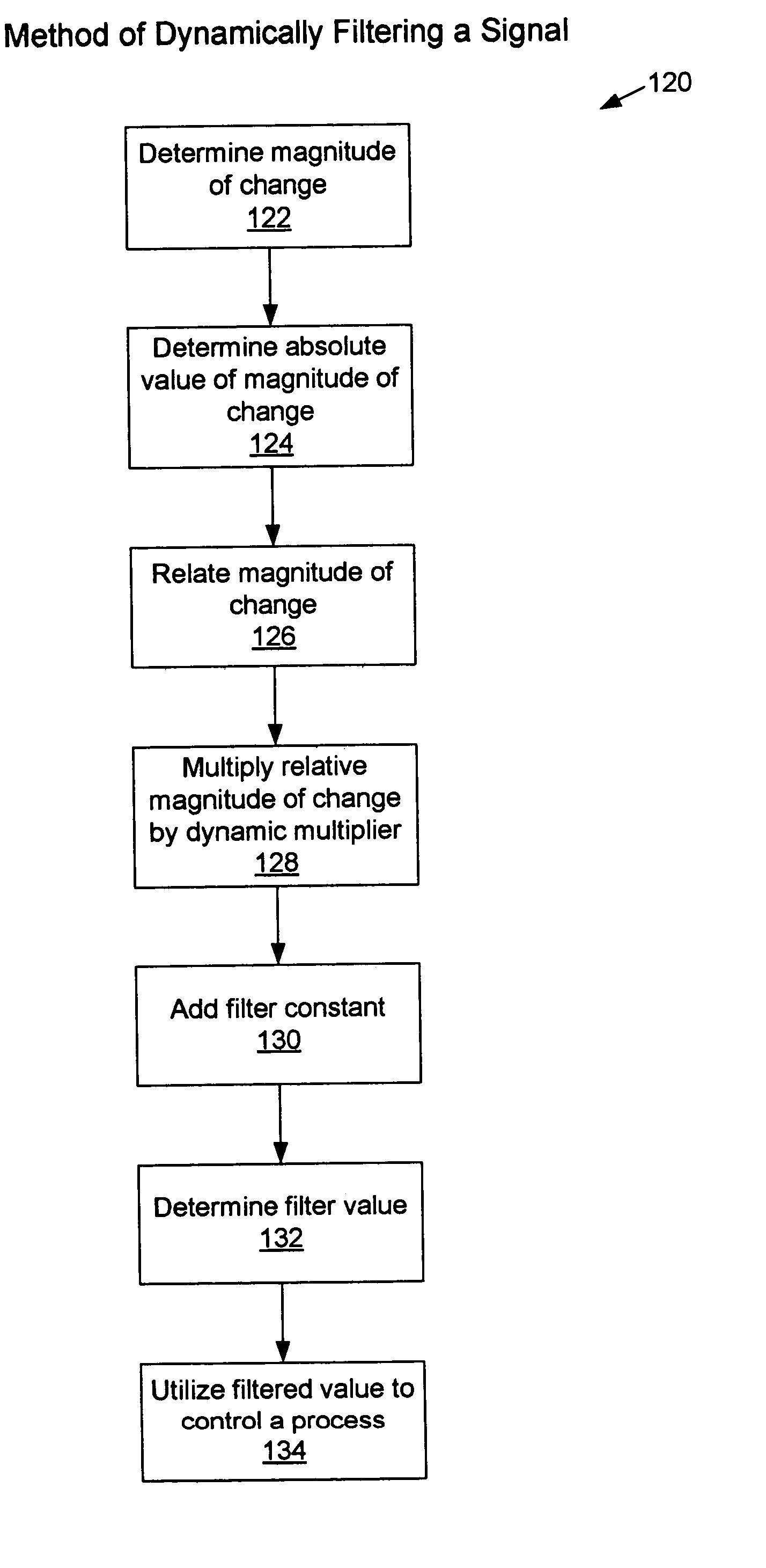
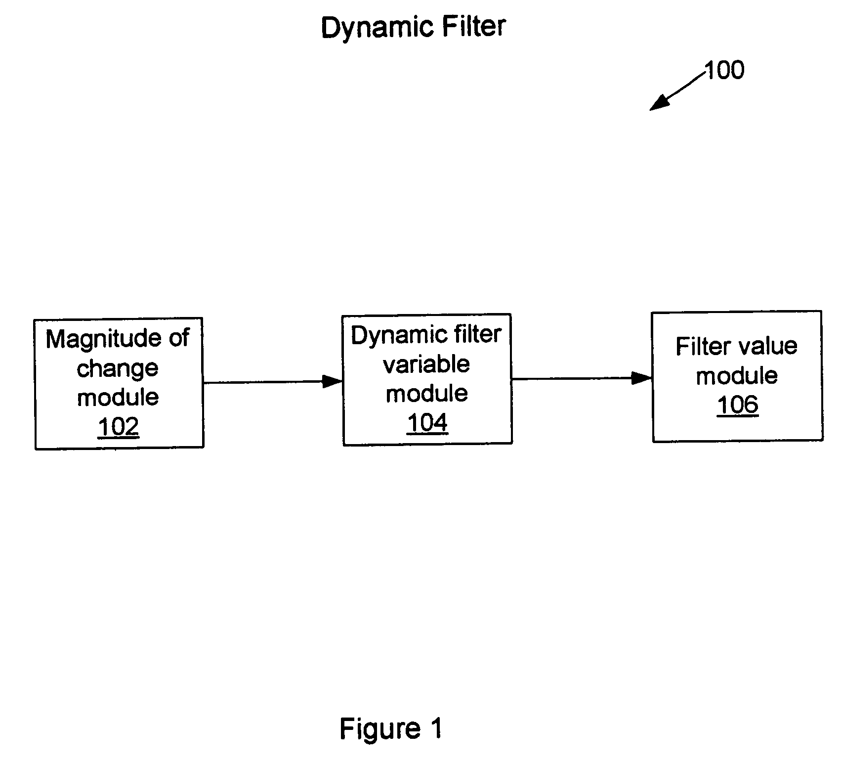
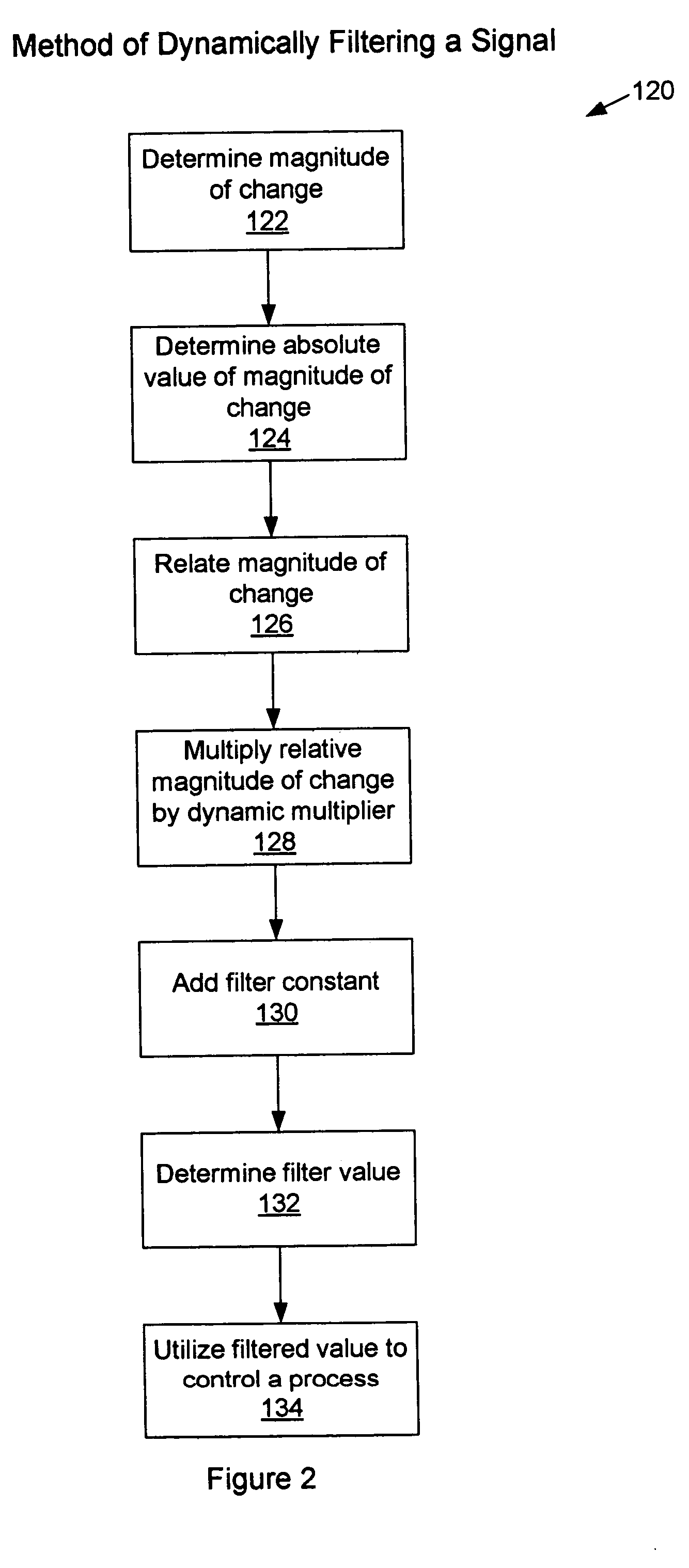
[0023] Reference will now be made to embodiments of systems, apparatuses, and methods to filter a signal to minimize small signal fluctuations while reacting quickly to larger signal fluctuations. Examples of such filter embodiments are illustrated in the accompanying drawings. Details, features, and advantages of those filter embodiments will become further apparent in the following detailed description of embodiments thereof.

[0024] Any reference in the specification to “one embodiment,”“a certain embodiment,” or a similar reference to an embodiment is intended to indicate that a particular feature, structure or characteristic described in connection with the embodiment is included in at least one embodiment of the invention. The appearances of such terms in various places in the specification are not necessarily all referring to the same embodiment. References to “or” are furthermore intended as inclusive so “or” may indicate one or another of the ored terms or more than one ored...


PUM


Abstract

A system, an apparatus, and a method for dynamically filtering a signal. The system, apparatus, and method include providing a portion of a previously determined value and a portion of a currently determined value, the portions depending on a magnitude of change between those previously and currently determined values.

Description

CROSS-REFERENCE TO RELATED APPLICATIONS [0001] Not applicable. STATEMENT REGARDING FEDERALLY SPONSORED RESEARCH [0002] Not applicable. BACKGROUND [0003] 1. Field of the Invention [0004] The disclosed invention relates to a filter in general and, in particular, to a filter to minimize small signal fluctuations while reacting quickly to larger signal fluctuations. [0005] 2. Description of the Background [0006] A filter, as the term is used in the signal conditioning technology, may suppress noise existing on a signal or may average an oscillating or unsteady signal or may do both simultaneously. Such a filter may be implemented in software where, for example, portions of a signal that has been converted to digital information may be manipulated by way of instructions executed by a processor. Such a filter may alternately be implemented in hardware that may, for example, manipulate an analog signal carrying analog or digital information directly. When implemented in hardware, the filte...

Claims


Application Information

Patent Timeline
IPC IPC(8): H03H17/02
CPCH03H17/0261
Inventor CHATFIELD, GLEN F.WELLS, DALE K.
Owner OPTIMUM POWER TECH LP
Why Eureka
Try Eureka