Input stage threshold adjustment for high speed data communications

a high-speed data and threshold adjustment technology, applied in the field of improving can solve the problems of data being distorted during transmission between a transmitter and a receiver, affecting the timing characteristics of these positive and negative components, and affecting the reliability of data transmission. , to achieve the effect of increasing the reliability of data transmission

Inactive Publication Date: 2005-07-21
ALTERA CORP
View PDF8 Cites 22 Cited by
  • Summary
  • Abstract
  • Description
  • Claims
  • Application Information

AI Technical Summary

Benefits of technology

[0008] The present invention increases the reliability of data transmissions. More particularly, the present invention corrects an asymmetrical signal or, alternatively, an off-centered signal-eye that may occur as the result of certain types of timing distortions. Such timing distortions may include, for example, elongated and / or narrowed negative and positive signal components. Correction techniques may include adjusting the received signal with respect to the signal-eye or, alternatively, directly adjusting the signal-eye (e.g., the voltage threshold of the CDR). The object of both is to create a symmetrical signal with respect to the signal-eye or, alternatively, a centered signal-eye with respect to the received signal.

Problems solved by technology

Data is occasionally distorted during transmission between a transmitter and receiver.
Such distortions may occur as the result of, for example, noisy electronics, single-ended signal processing, PCB and package attenuation and reflection, and imperfections or mismatches in transmission lines.
Signal distortions, however, may change the timing characteristics of these positive and negative components.
However, if the negative and / or positive component of the received signal is skewed, then the zero-crossings for that received signal may also be skewed.
Thus, the line intersecting the zero-crossings may be distorted such that the signal-eye is not centered properly with respect to the received signal.
Moreover, the average voltage of the received signal, which is proportional to the signal's average power, may be distorted.
These types of distortions often result in asymmetry in the received signal with respect to the receiver's signal-eye.
Even if only a single logical “1” or “0” is misidentified, then the entire system relying on the correct identification of that bit may operate improperly or, in a worst case scenario, not operate at all.

Method used


Image

  • Input stage threshold adjustment for high speed data communications
  • Input stage threshold adjustment for high speed data communications
  • Input stage threshold adjustment for high speed data communications

Examples


Embodiment Construction

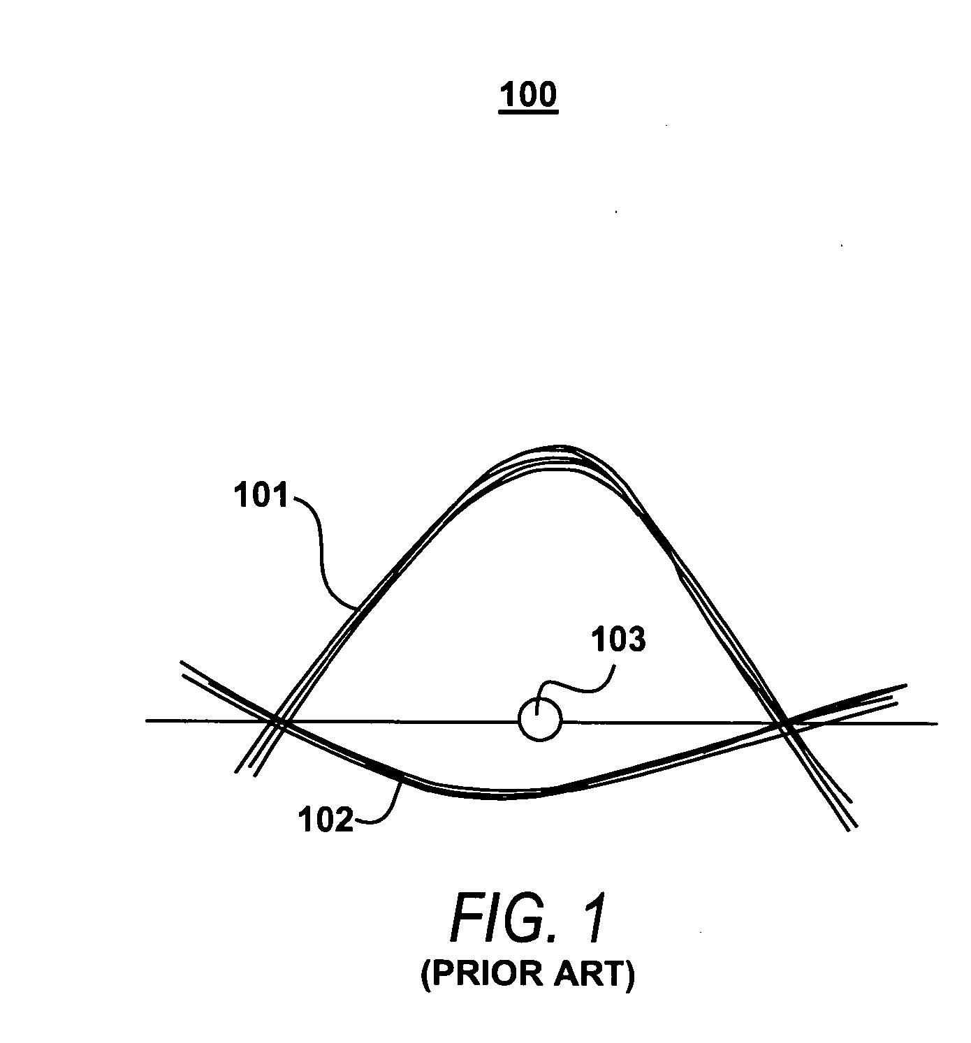
[0023] Turning first to FIG. 1, the principles of prior art signal-eye centering technique 100 is illustrated. Received positive signal component 101 and negative signal component 102 form a bit of the received signal. Signal-eye 103 is positioned vertically in-line with the zero-crossings of signal components 101 and 102. Prior art CDR circuitry (not shown) measures the average power of signal components 101 and 102 and compares them against the voltage of signal-eye 103 to determine if the received bit is a logical “1” or “0.” As stated, prior art signal-eye centering technique 100 does not correct for certain types of timing distortions. Moreover, the prior art does not provide for any correction or adjustment whatsoever.

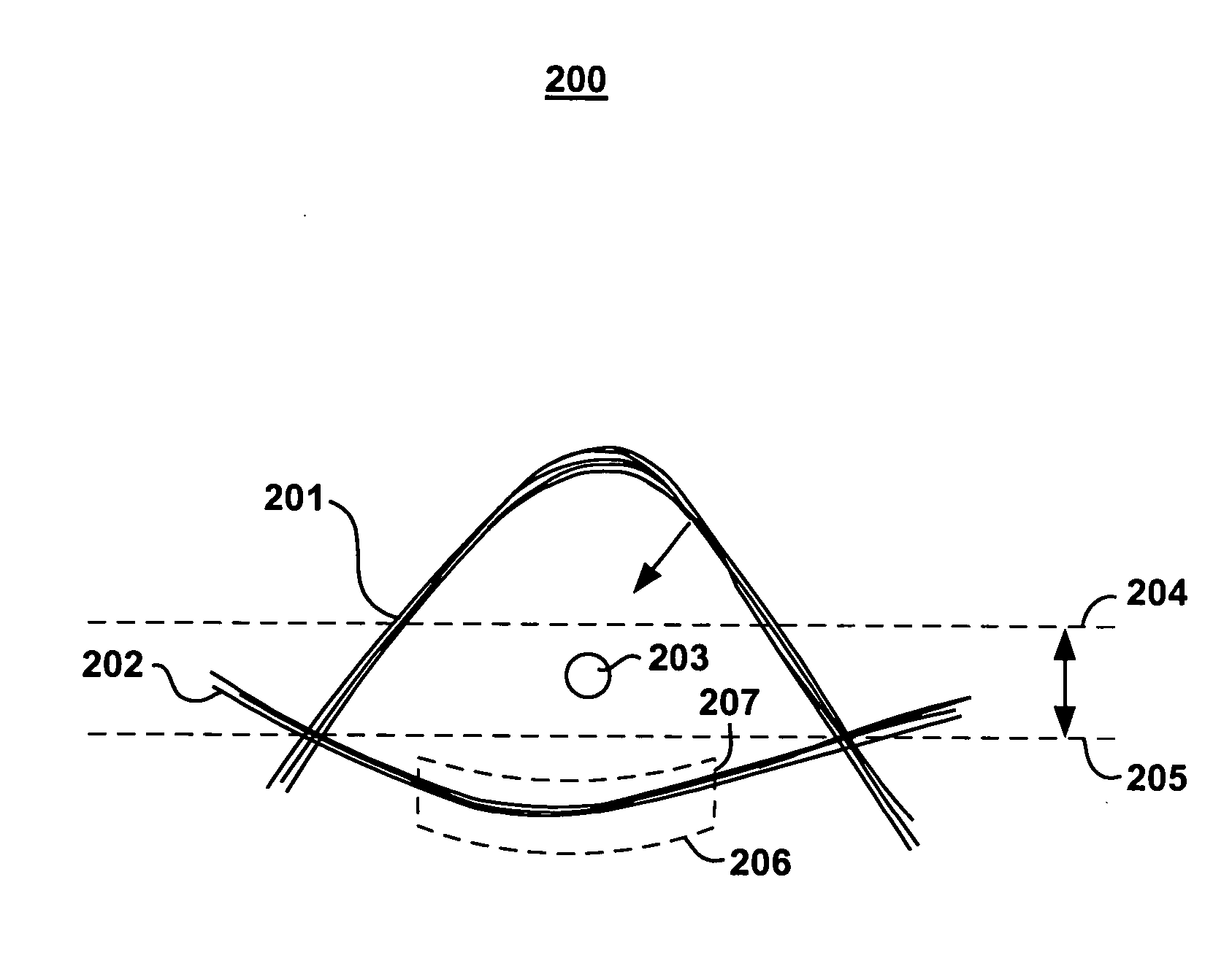
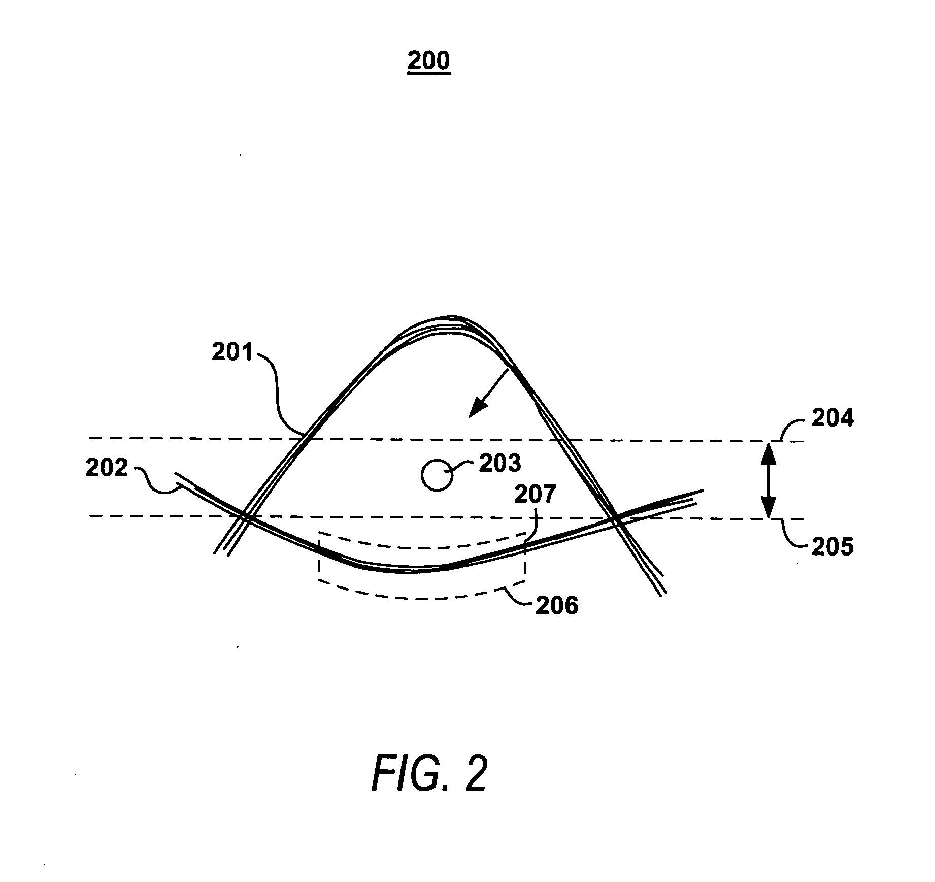
[0024]FIG. 2 illustrates the principles of signal-eye correction technique 200 constructed in accordance with the principles of the present invention. Signal-eye 203 is provided to determine if the received signal bit, defined by positive signal component 201 an...


PUM


Abstract

Systems and methods for correcting distortions in transmitted signals are provided. More particularly, systems and methods for correcting the asymmetry that may occur between a receiver's signal-eye and a distorted signal are provided. One technique centers the signal-eye, with respect to the received signal, by adjusting the voltage threshold of the signal-eye in the receiver's clock and data recovery decision circuit. Another technique centers the signal-eye, with respect to the received signal, by shaping the voltage of the received signal. A current-mode logic circuit is provided to shape the voltage of the received signal by sinking current from the received signal.

Description

BACKGROUND OF THE INVENTION [0001] This invention relates to improving the reliability of data transmissions. More particularly, this invention relates to adjusting the centering of a signal-eye in a receiver. [0002] Data is occasionally distorted during transmission between a transmitter and receiver. Such distortions may occur as the result of, for example, noisy electronics, single-ended signal processing, PCB and package attenuation and reflection, and imperfections or mismatches in transmission lines. [0003] Generally, a receiver's signal-eye represents the voltage threshold of a received signal that separates a logical “0” from a logical “1.” Traditionally, this voltage threshold is compared to a portion (e.g., a bit) of the received signal to determine if that portion represents a logical “1” or a logical “0.” For example, a received signal may have a logical “0” defined ideally as 0.8 volts, while a logical “1” is defined ideally as 1.2 volts. In this example, an appropriate...

Claims


Application Information

Patent Timeline
Patent Type & Authority Applications(United States)
IPC IPC(8): G01R31/317G06F11/00
CPCG01R31/31711
Inventor BAIG, MASHKOORWANG, SHOUJUNKWASNIEWSKI, TADMEI, HAITAOBEREZA, BILL
Owner ALTERA CORP
Why Eureka
Try Eureka