Method and apparatus for dataflow creation and execution

a dataflow and data technology, applied in the field of methods and systems, can solve the problems of complex problems, new business-critical technical computing problems, and the individual computational steps themselves are often computer intensive and time-consuming

Inactive Publication Date: 2005-07-21
DATACLOUD TECH LLC
View PDF11 Cites 90 Cited by
  • Summary
  • Abstract
  • Description
  • Claims
  • Application Information

AI Technical Summary

Benefits of technology

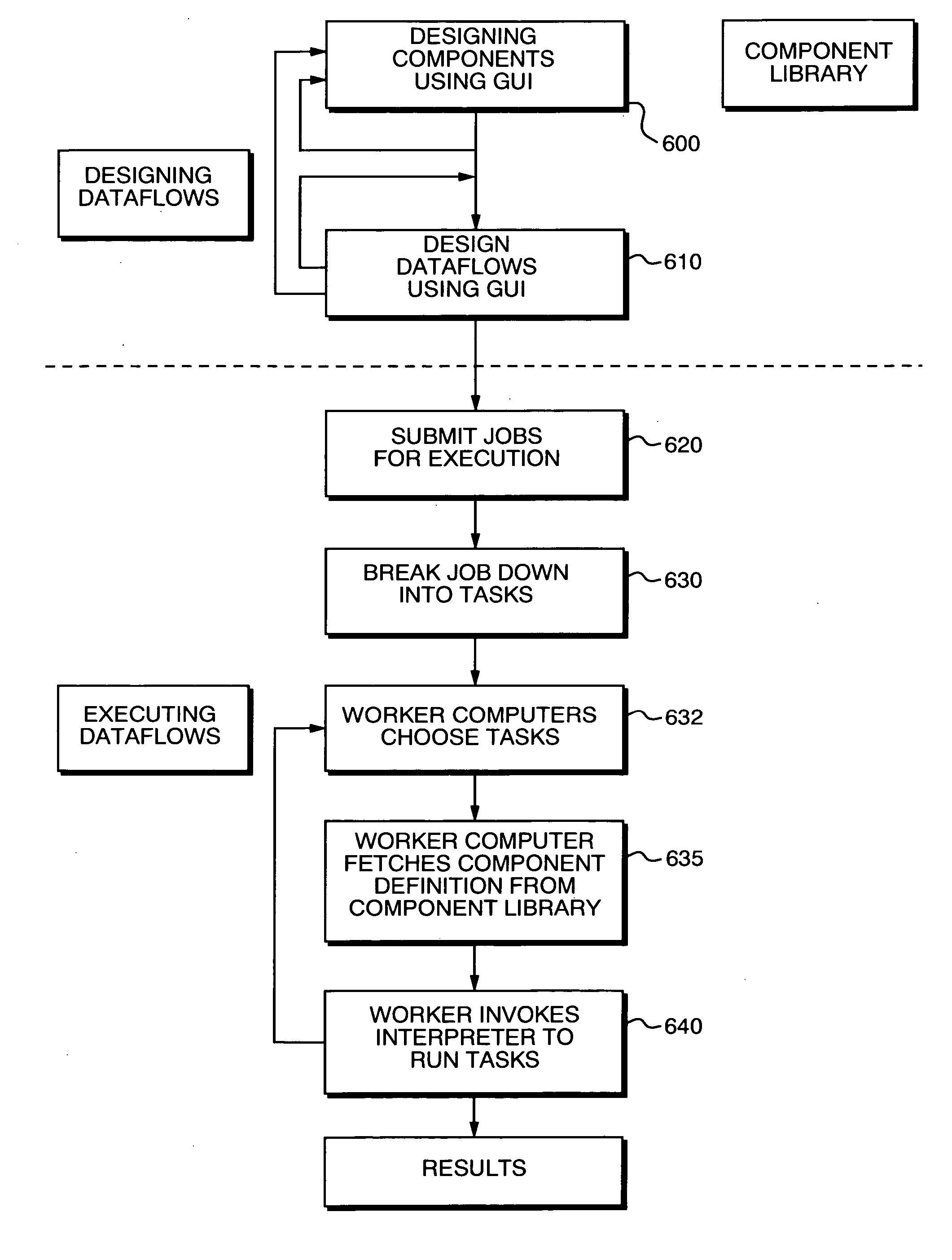
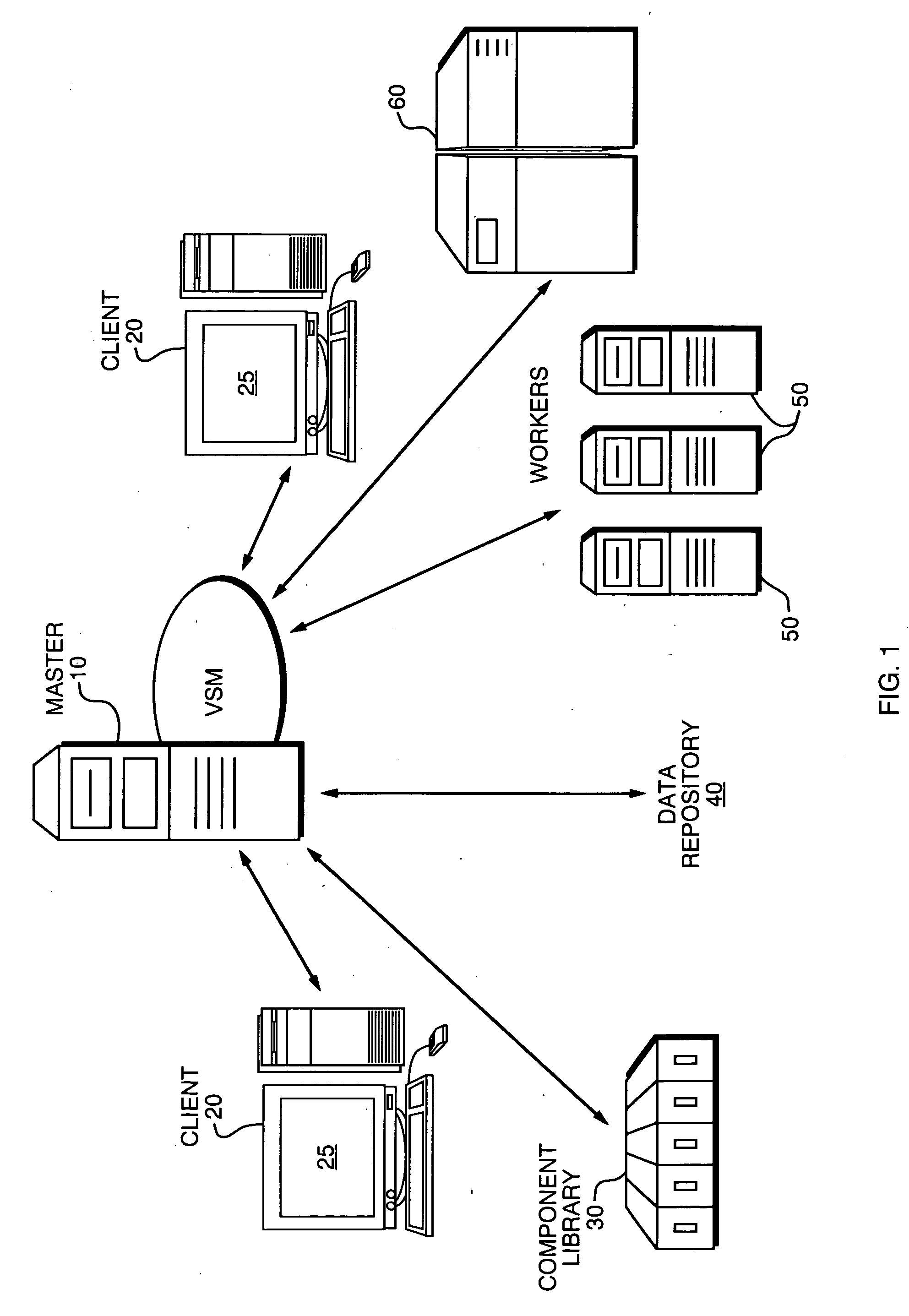
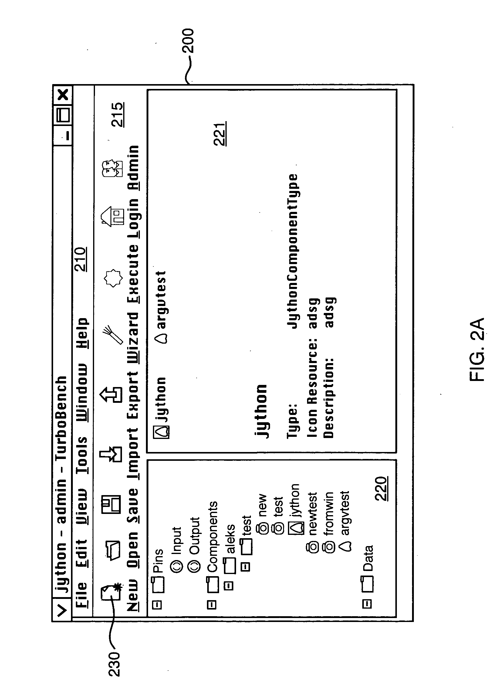
[0014] The present invention provides for a method for creating and executing a computer workflow using a graphical user interface. A plurality of executable components is defined wherein the executable components are based on an input, an output, metadata and a sub-interpreter. Each of the executable components represents a computer-implemented computational process that is performed on one or more inputs to the executable component and that generates one or more outputs based on a predefined computational algorithm. A graphical user interface is defined that allows a user to visually create the computer workflow on a user display by selecting from a library of said executable components. The user graphically connects one or more input terminals of selected executable components with one or more output terminals of second selected executable components. For each selected executable component, the one or more input terminals graphically correspond to the one or more inputs to the predefined computational algorithm associated with the executable component. The one or more output terminals graphically correspond to the one or more outputs generated by the predefined computational algorithm associated with the executable component. At least one selected executable component comprises a splitter component having one or more splitter input terminals that graphically correspond to a splitter input to a splitter algorithm associated with the one splitter component. Each splitter input terminal receives its splitter input at a single splitter input time. Each splitter component has one or more splitter output terminals that graphically correspond to a splitter output generated by the splitter algorithm associated with the splitter component. The splitter output terminals produce splitter output at a plurality of splitter output times. The splitter output

Problems solved by technology

For companies in these industries—including the biotechnology, pharmaceutical, geophysical, automotive, and aerospace industries, among others—a new class of business-critical technical computing problems has arisen.
These problems are complex, with solutions often involving multiple computational steps with large quantities of data passing from one step to the next.
In addition, the individual computational steps themselves are often computer intensive and very time consuming.
These dataflows, which are both computationally intensive and logistically complex, are essential parts of the R&D process, because without them, it would be impossible to adequately investigate the large amount of data coming out of modern, highly automated laboratories.
The new class of technical computing problems described above pose a number of substantial computational challenges.
First, they require huge amounts of CPU horsepower and other computational resources.
However, individual clusters are insufficient to meet the voracious demands of complex technical computing dataflows.
Computing grids have a wealth of resources—CPUs, storage, communication, etc.—that may be applied to technical computations, but management of such diverse collections of resources is difficult, and effective software solutions are only now beginning to appear.
A second major challenge arises because solutions to the new class of problems must access and integrate massive amounts of data from large numbers of distinct sources.
Algorithms for technical computation traditionally assume that all required data is stored locally and that the costs of data access are almost always dominated by the costs of computation.
For such problems, the costs of accessing the data and integrating it into the computational process may easily outstrip the costs of the computations themselves.
Finally, a third major challenge relates to the way that users manage the execution of the kind of large, complex dataflows required to s

Method used


Image

  • Method and apparatus for dataflow creation and execution
  • Method and apparatus for dataflow creation and execution
  • Method and apparatus for dataflow creation and execution

Examples


example 1

[0059] The following provides a detailed example applying the method of the present invention to a dataflow for a protein sequence classification. An important problem for many bioinformatics researchers is the classification of groups of amino-acid sequences into fine-grained categories (subfamilies) whose members have similar physical properties and may be metabolically related. For example, each of the sequences involved might be what is known as a structural domain of some protein in a certain protein family, and the goal might be to identify which of the sequences are likely to have similar function. For a typical problem, there may be tens of thousands of sequences involving millions of amino acids.

[0060] A number of approaches to this sequence classification problem are possible, but the one considered here creates the subfamilies by identifying “seed pairs” (highly similar pairs of sequences) and collecting other sequences around each seed pair based on a model of the natur...


PUM


Abstract

A method for creating and executing a computer workflow using a graphical user interface. A plurality of executable components is defined wherein the executable components are based on an input, an output, metadata and a sub-interpreter. Each of the executable components represents a computer-implemented computational process that is performed on one or more inputs to the executable component and that generates one or more outputs based on a predefined computational algorithm. A graphical user interface is defined that allows a user to visually create the computer workflow on a user display by selecting from a library of said executable components. The user graphically connects one or more input terminals of selected executable components with one or more output terminals of second selected executable components. For each selected executable component, the one or more input terminals graphically correspond to the one or more inputs to the predefined computational algorithm associated with the executable component. The one or more output terminals graphically correspond to the one or more outputs generated by the predefined computational algorithm associated with the executable component.

Description

REFERENCE TO RELATED APPLICATIONS [0001] This application claims the benefit of U.S. Provisional Application No. 60 / 523,570 filed on Nov. 20, 2003, entitled “Method and Apparatus for Dataflow Creation and Execution” and U.S. patent application Ser. No. 10 / 610,133 entitled “Method and Apparatus for Dataflow Creation and Execution” filed Jun. 30, 2003.FIELD OF THE INVENTION [0002] The invention relates to methods and systems for creating and executing a computer dataflow using a graphical user interface. BACKGROUND OF THE INVENTION [0003] In many industries, information technology platforms for technical computing have become key differentiators and drivers of business growth. For companies in these industries—including the biotechnology, pharmaceutical, geophysical, automotive, and aerospace industries, among others—a new class of business-critical technical computing problems has arisen. These problems are complex, with solutions often involving multiple computational steps with lar...

Claims


Application Information

Patent Timeline
IPC IPC(8): G06F17/30G06Q10/00
CPCG06Q10/06
Inventor BJORNSON, ROBERT DEANMCCUSKER, JAMES PATRICK IIIWING, JAMES EDWINSHERMAN, ANDREW H.WESTON, STEPHEN B.
Owner DATACLOUD TECH LLC
Why Eureka
Try Eureka