Planetary differential screw type rotary/linear motion converter

Inactive Publication Date: 2005-07-28
TOYOTA JIDOSHA KK
View PDF11 Cites 72 Cited by
  • Summary
  • Abstract
  • Description
  • Claims
  • Application Information

AI Technical Summary

Benefits of technology

[0018] Based on the knowledge acquired as a result of the extensive investigations performed by the inventor, it is a principal object of the present invention to provide a rotary/linear motion converter which has a screw shaft, planetary screw rollers, and a roller nut, and provides a conversion of a rotary movement to a linear movement at a lar

Problems solved by technology

However, in the conventional screw type rotary/linear motion converter described in the above-mentioned JP 10-196756, no relative thrust or linear displacement occurs between the planetary screw rollers and the roller nut, and therefore, the linear displacement of the screw shaft per one revolution of the roller nut can not be made small, and there is a problem that the assembling is not convenient.
However, when this device is used as a rotary/linear motion converter, the operational performance changes according to a load applied thereto, so that the ratio of conversion between the rotary motion and the linear motion (output displacement per unit input displacement) fluctuates, and therefore, there is a problem that a rotary motion is not correctly converted into a linear motion with a definite c

Method used


Image

  • Planetary differential screw type rotary/linear motion converter
  • Planetary differential screw type rotary/linear motion converter
  • Planetary differential screw type rotary/linear motion converter

Examples


first embodiment

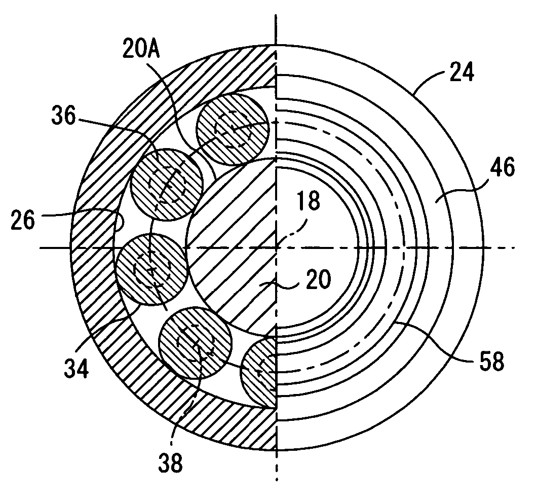
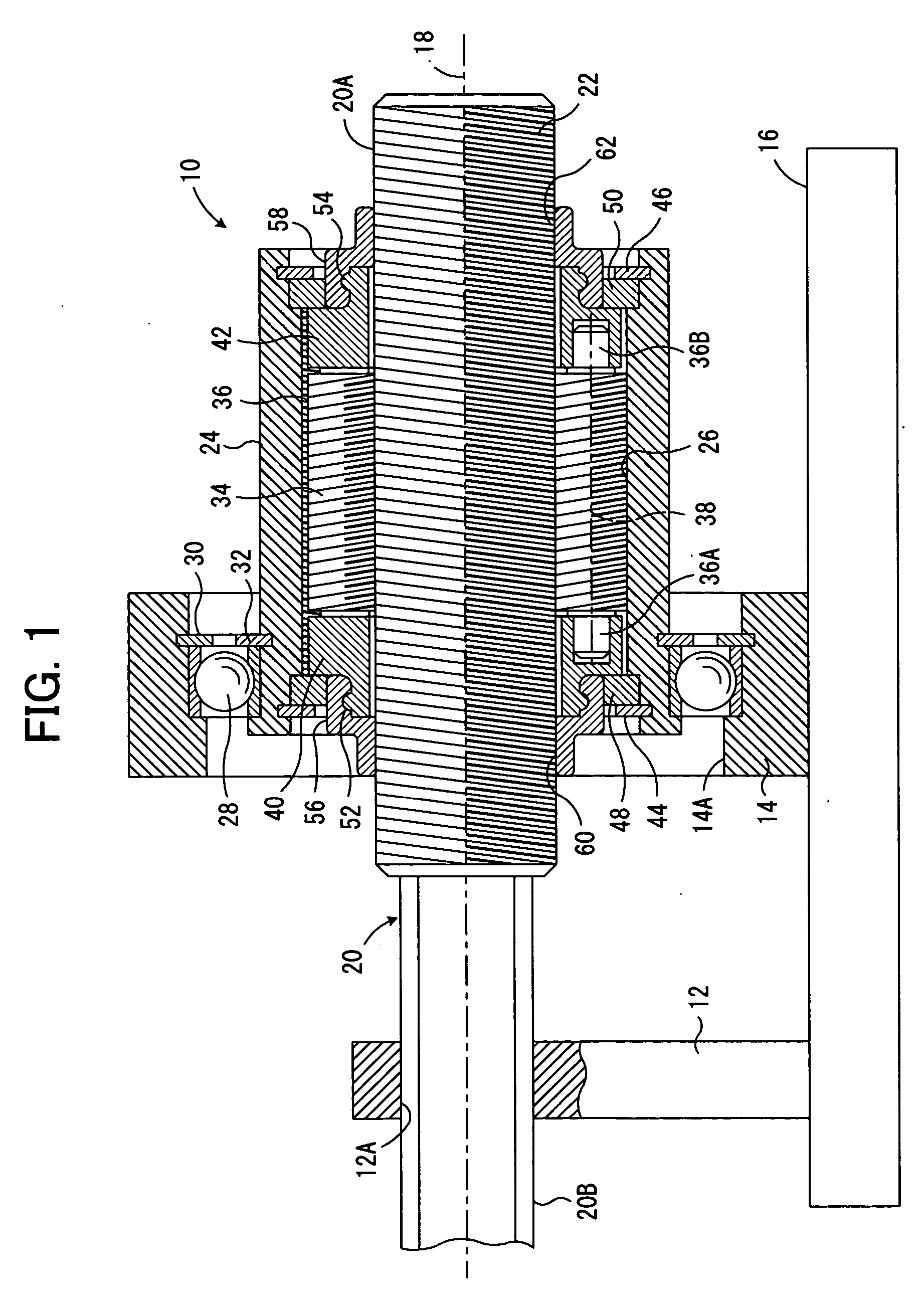
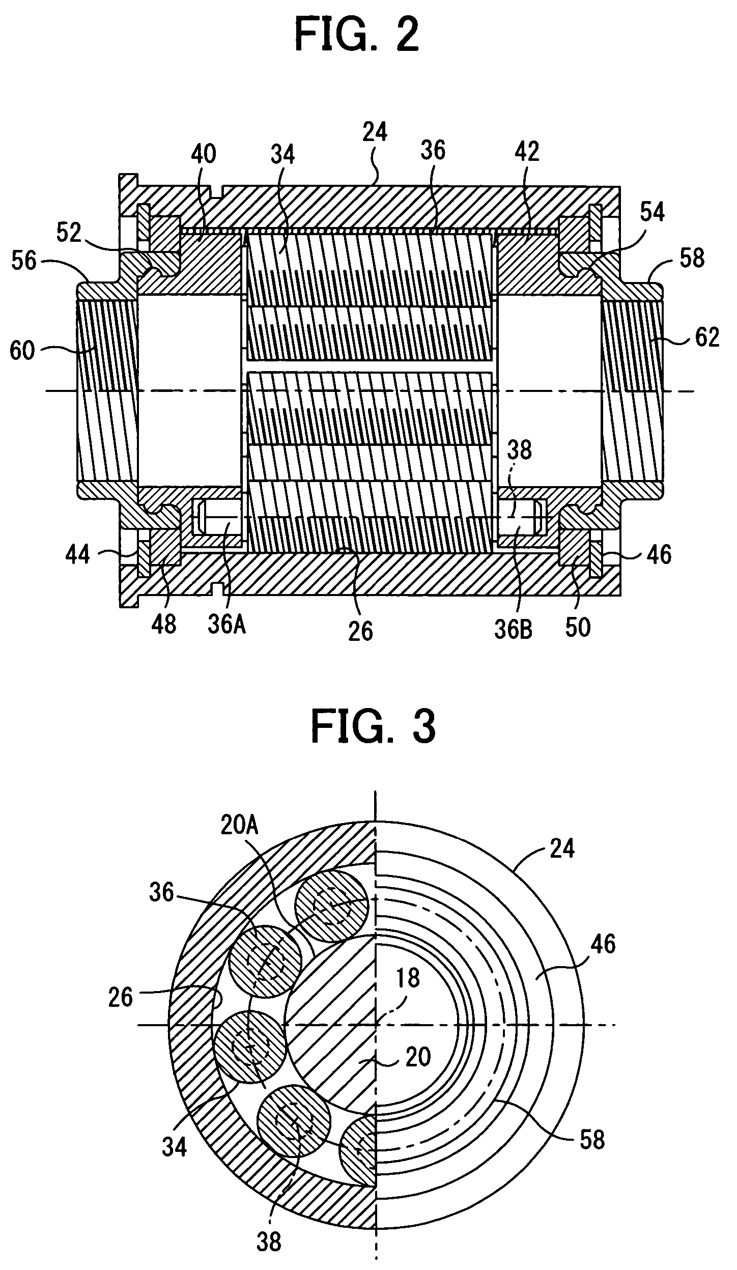
[0109]FIG. 1 is a longitudinal sectional view showing the first embodiment of the planetary differential screw type rotary / linear motion converter according to the present invention constructed to convert a rotary motion of a roller nut to a linear motion of a screw shaft; FIG. 2 is a plane sectional view showing the main part of the first embodiment in a condition that the screw shaft is removed; FIG. 3 shows a right side view of the first embodiment (right) and a section perpendicular to an axis (left), and FIG. 4 is a left side view of the first embodiment.

[0110] In these drawings, 10 generally designates a planetary differential screw type rotary / linear motion converter, supported by a base 16 via two supporting columns 12 and 14. The rotary / linear motion converter 10 comprises a screw shaft 20 extending along an axis 18 and having a screw section 20A, a male thread 22, and a shaft portion 20B prevented against rotation and formed integrally with the screw section 20A.

[0111] T...

second embodiment

[0147]FIG. 7 is a longitudinal sectional view showing a second embodiment of a planetary differential screw type rotary / linear motion conversion device according to the present invention constructed to convert a rotary motion of a roller nut to a linear motion of a screw shaft. In FIG. 7, the members which are the same as those shown in FIG. 1 are designated by the same reference numerals.

[0148] In this second embodiment, the screw portion 20A is provided only at a central portion of the larger diameter portion 20C corresponding to the screw portion 20A of the first embodiment opposing the planetary screw rollers 36, with no male thread 22 being formed at opposite end portions of the larger diameter portion 20C. Further, the carriers 40 and 42 are mounted so as not to be movable in the linear directions relative the larger diameter portion 20C by C-rings 44 and 46 and stopper rings 48 and 50 fixed to the larger diameter portion 20C.

[0149] Further, the carriers 40 and 42 are formed...

third embodiment

[0155]FIG. 8 is a sectional view showing a third embodiment of the planetary differential screw type rotary / linear motion conversion device according to the present invention constructed as a modification of the first embodiment. In FIG. 8, the members corresponding to those shown in FIG. 1 are designated by the same reference numerals as in FIG. 1.

[0156] The motion conversion device 10 of this third embodiment has a first motion conversion unit 10L and a second motion conversion unit 10R each having the same construction as the motion conversion device 10 of the above-mentioned first embodiment, the first and the second motion conversion units 10L and 10R being shaped as reflected in the mirror relative to one another along the axis 18. The male thread 22L of the screw shaft 20L, the male thread 34L of the planetary screw roller 36L and the female thread 26L of the roller nut 24L of the first motion conversion unit 10L and the male thread 22R of the screw shaft 20R, the male threa...


PUM


Abstract

The object of the present invention is to convert a rotary motion into a linear motion more precisely than ever by utilizing the principles of a planetary gear mechanism and a differential screw. The rotary/linear motion conversion device of the present invention has a screw shaft 20, a plurality of planetary screw rollers 36 mating with the screw shaft therearound, and a roller nut 24, with the screw shaft 20 and the planetary screw rollers 36 mating with one another by threads of opposite winding directions, while the planetary screw rollers 36 and the roller nut 24 mate with one another by threads of a same winding direction, wherein the respective threads are of a common pitch, and the number of co-extending threads of either of the screw nut and the roller nut is varied from that which satisfies the condition that neither of the screw shaft nor the roller nut moves linearly relative to one another in spite of a relative rotation thereof along with rotation and revolving of the planetary screw rollers relative to the screw shaft and the roller nut with no slippage.

Description

BACKGROUND OF THE INVENTION [0001] 1. Field of the Invention [0002] This invention relates to a rotary / linear motion converter, and more specifically, to a planetary differential screw type rotary / linear motion converter which converts a rotary motion into a linear motion. [0003] 2. Description of the Prior Art [0004] As one of a screw type rotary / linear motion converter for converting a rotary motion into a linear motion, there has been known a planetary screw type rotary / linear motion converter having a screw shaft, planetary screw rollers positioned around and mating with the screw shaft, and a roller nut surrounding the screw shaft and the planetary screw rollers and mating with the latter, as described, for example, in Japanese Patent Laid-Open Publication No. 10-19675. [0005] According to such a screw type rotary / linear motion converter, when one of the screw shaft and the roller nut is rotated, the planetary screw rollers rotate, so that the other of the screw shaft and the r...

Claims


Application Information

Patent Timeline
IPC IPC(8): F16H25/22
CPCY10T74/19795F16H25/2252
Inventor SUGITANI, NOBUYOSHI
Owner TOYOTA JIDOSHA KK
Why Eureka
Try Eureka