Muffler of Internal Combustion Engine

Inactive Publication Date: 2008-02-14
TOYOTA JIDOSHA KK
View PDF18 Cites 0 Cited by
  • Summary
  • Abstract
  • Description
  • Claims
  • Application Information

AI Technical Summary

Benefits of technology

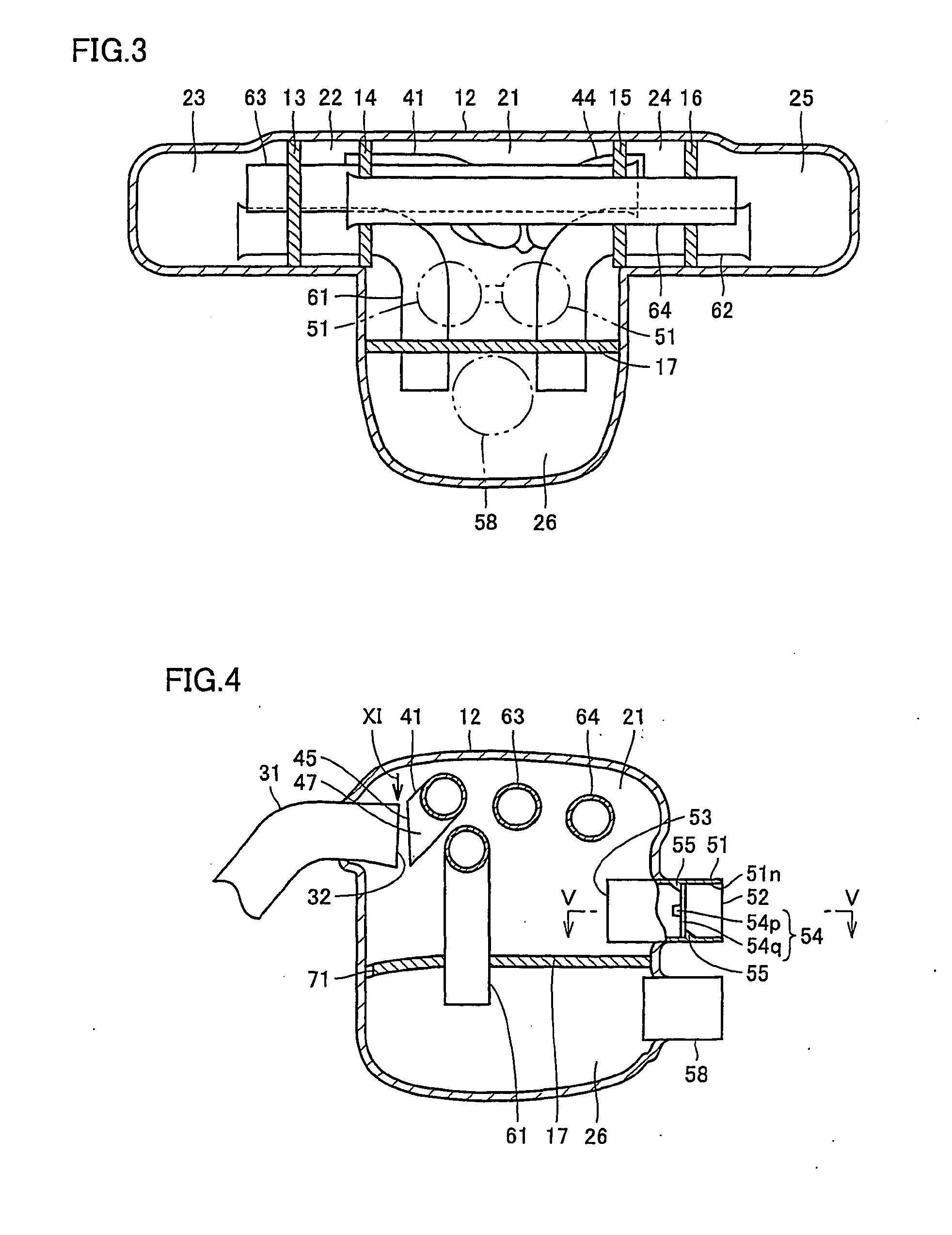
[0008] Since the slope extends in a direction differing from the predetermined direction in accordance with the muffler of the internal combustion engine configured as set forth above, the exhaust gas flowing into the second opening from the first opening collides against the internal wall of the internal duct at the slope. At this stage, the exhaust gas is cooled, whereby the water vapor in the exhaust gas is condensed into a liquid, i.e. condensed liquid. Since the slope inclines vertically downwards towards the second opening, the condensed liquid runs down the slope to be emitted into the internal room from the second opening. In accordance with the present invention, exhaust gas having the ratio of water vapor included therein greatly reduced is delivered to the site where the valve is disposed. Accordingly, generation of condensed liquid from exhaust gas at the site where the valve is disposed is suppressed to prevent disturbance of proper driving of the valve caused by freezing of condensed liquid.
[0009] Preferably, the lower end position of the mouth of second opening is located deviating from the mouth of the first opening, when viewed along the predetermined direction. In accordance with the muffler of an internal combustion engine configured as set forth above, disturbance of the flow of condensed liquid from the exhaust gas generated at the slope, when flowing from the second opening to the internal room, caused by the exhaust gas flowing from the first opening to the second opening, can be prevented. Thus, the condensed liquid from the exhaust gas can be emitted efficiently into the internal room.
[0010] Preferably, the internal duct is formed bending at the slope. In accordance with the muffler of an internal combustion engine configured as described above, the exhaust gas flowing from the first opening to the second opening further collides against the inner wall of the internal duct where the slope bends. Therefore, the ratio of water vapor included in the exhaust gas can be further reduced.
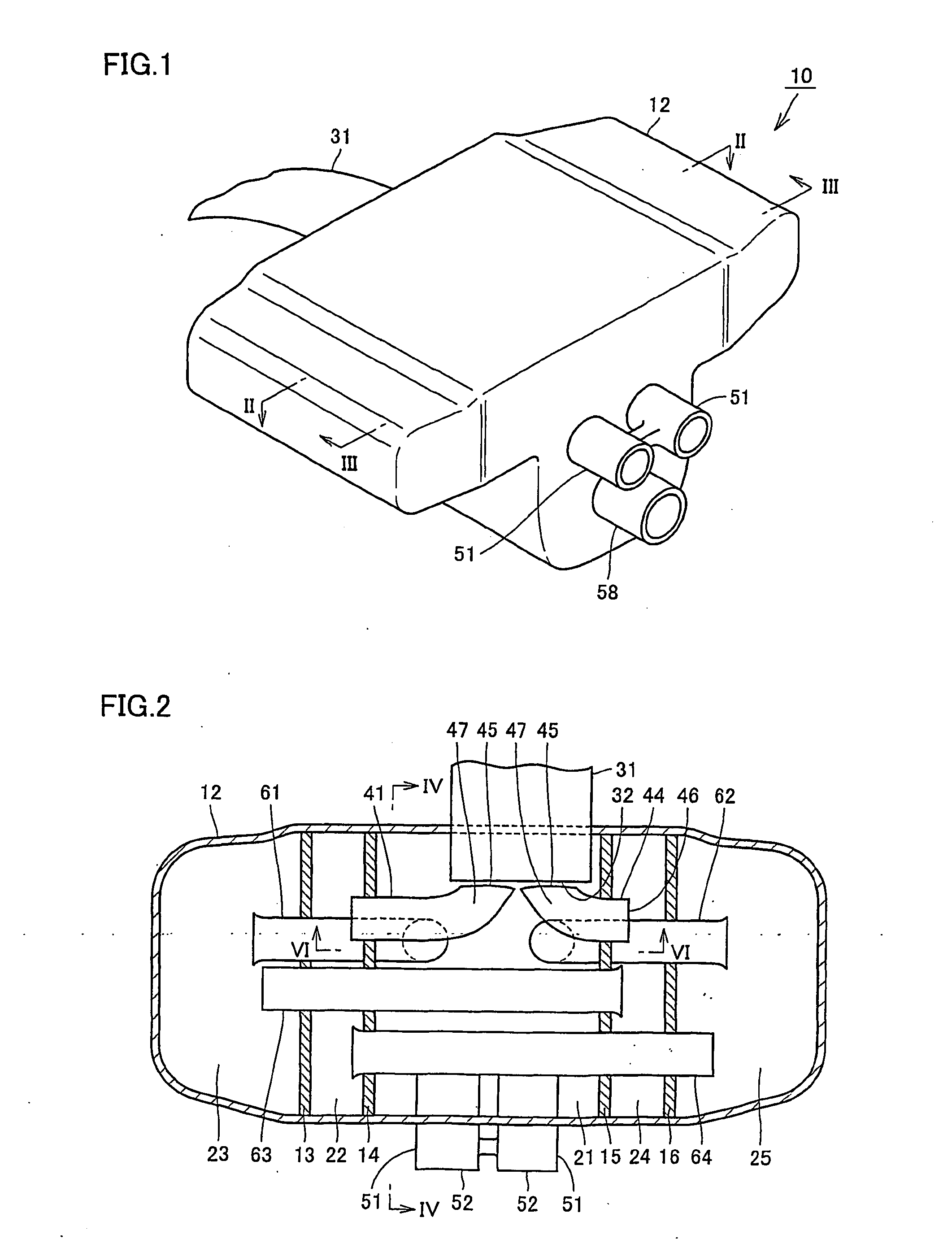
[0011] Further preferably, the inlet pipe is formed inclined vertically downwards towards the first opening. A trench is formed at the bottom of the inner wall of the inlet pipe. By such a configuration, the condensed liquid of the exhaust gas generated at the inlet pipe flows towards the first opening, and can be emitted into the internal room from the first opening. Since the condensed liquid is collected at the trench formed at the bottom of the inner wall, the flow of condensed liquid is facilitated.
[0012] The muffler of an internal combustion engine further includes a first outlet pipe having a valve provided on a conduit to emit exhaust gas from the internal room. Preferably, the first outlet pipe is formed inclined vertically downwards as becoming distant from the valve. A trench is formed at the bottom of the inner wall of the first outlet pipe. By such a configuration, the condensed liquid of exhaust gas at the first outlet pipe, when generated, can be made to flow farther away from the valve. Since the condensed liquid is collected at the trench formed at the bottom of the internal wall, the flow of condensed liquid is facilitated.
[0015] In accordance with the present invention, a muffler of an internal combustion engine having proper driving of a valve ensured can be provided.

Problems solved by technology

A muffler provided with such a valve is disadvantageous in that condensed water of the exhaust gas remains in the proximity of the valve after the engine has been started.
If the engine is then stopped and left under such a state, the condensed water will freeze at low temperature conditions such as during wintertime, leading to the possibility of malfunction in the valve.

Method used


Image

  • Muffler of Internal Combustion Engine
  • Muffler of Internal Combustion Engine
  • Muffler of Internal Combustion Engine

Examples


Embodiment Construction

[0026] An embodiment of the present invention will be described hereinafter with reference to the drawings.

[0027] Referring to FIG. 1, a variable muffler 10 includes the main body of a muffler, i.e. a muffler body 12, an inlet pipe 31 connected to muffler body 12 at the front side of the vehicle, and also an outlet pipe 58 and two outlet pipes 51 with valves, connected to muffler body 12 at the rear side of the vehicle. Muffler body 12 is formed of a metal such as stainless steel or titanium. Inlet pipe 31 communicates with an internal combustion engine such as a gasoline engine or diesel engine. The two valve-added outlet pipes 51 extend in parallel spaced apart from each other in the horizontal direction.

[0028] Referring to FIGS. 2-4, muffler body 12 takes a housing configuration, and includes partitions 13-17. Partition 17 extending in the horizontal direction and partitions 14 and 15 extending in the vertical direction and spaced apart from each other constitute a muffler cham...


PUM


Abstract

A variable muffler corresponds to a muffler of an internal combustion engine including a variable valve that controls the flow of exhaust gas. The variable muffler includes a muffler body forming a muffler chamber, an inlet pipe with an opening at the muffler chamber to direct the flow of exhaust gas from the opening towards the muffler chamber, and a muffler-in pipe arranged in the muffler chamber. The muffler-in pipe includes an opening facing the opening at the muffler chamber, and into which the exhaust gas output from the opening flows in a predetermined direction. The muffler-in pipe further includes a slope inclining vertically downwards towards the opening, and extending in a direction different from the predetermined direction. By such a configuration, a muffler of an internal combustion engine having proper driving of the valve ensured can be provided.

Description

TECHNICAL FIELD [0001] The present invention generally relates to a muffler of an internal combustion engine, and more particularly, a muffler of an internal combustion engine with a valve for controlling the flow of exhaust gas. BACKGROUND ART [0002] A conventional muffler of an internal combustion engine is disclosed in, for example, Japanese Patent Laying-Open No. 2000-54822, directed to reducing the size without degradation in the muffling performance. The muffler disclosed in this publication includes a control valve that opens when the pressure of the exhaust gas in the muffler chamber exceeds a predetermined level. A valve opening that communicates with the muffler chamber and a sheet-like valve capable of deformation and provided so as to close the valve opening, constitute the control valve. [0003] Japanese Patent Laying-Open No. 9-32590 discloses a throttle valve device for an internal combustion engine, directed to allowing resin-molding of the throttle body and preventin...

Claims


Application Information

Patent Timeline
IPC IPC(8): F01N1/08F01N13/00F01N99/00
CPCF01N1/084F01N2490/15F01N1/163F01N1/089
Inventor MABUCHI, TOMOKISAWADA, NORIHIKOMIZUNO, FUMIHIKO
Owner TOYOTA JIDOSHA KK
Why Eureka
Try Eureka