Methods for filtering fluids

a technology of filtering fluid and filtering medium, which is applied in the field of filtering fluid methods, can solve the problems of long time for filtration of some viscous samples, especially serum or plasma, and insufficient homogeneous distribution of filtrate volume through the plate, so as to achieve uniform filtering volume, improve filtering average volume, and reduce the effect of well-to-well filtering volume variability

Inactive Publication Date: 2005-07-28
MILLIPORE CORP
View PDF19 Cites 18 Cited by
  • Summary
  • Abstract
  • Description
  • Claims
  • Application Information

AI Technical Summary

Benefits of technology

[0009] The swinging bucket of the centrifuge can include a counterweight to prevent over rotation or control the pivot angle of the swinging bucket during centrifugation. The centrifuge can also include a “stop” to control the pivot angle of the swinging bucket during centrifugation. The centrifuge can also include a support assembly to hold the fluid filtering device at a fixed angle relative to the line of the centrifuge.
[0012] The present fluid filtering device has an advantage in that it can increase average volume filtered during centrifugation and the filtrate volume is substantially uniform with little well-to-well filtrate volume variability, thereby minimizing a “smile effect” as compared to a flat plate with all wells in the same orientation from the plane of the flat plate and that the plane of the flat plate is normal to the swing radius vector.
[0013] Using an angling mechanism can increase the average filtrate flow rate among a plurality of wells in a filtration well plate. This can be accomplished by angling the membranes of the wells at an angle relative to a line in a centrifuge or by angling the plate relative to a line in a centrifuge.

Problems solved by technology

Filtrations of some, especially viscous samples, (e.g. serum or plasma) can take a long time to collect even a minimum filtrate volume.
On the other hand, the volume of the filtrate is not homogeneously distributed through the plate.

Method used


Image

  • Methods for filtering fluids
  • Methods for filtering fluids
  • Methods for filtering fluids

Examples


Embodiment Construction

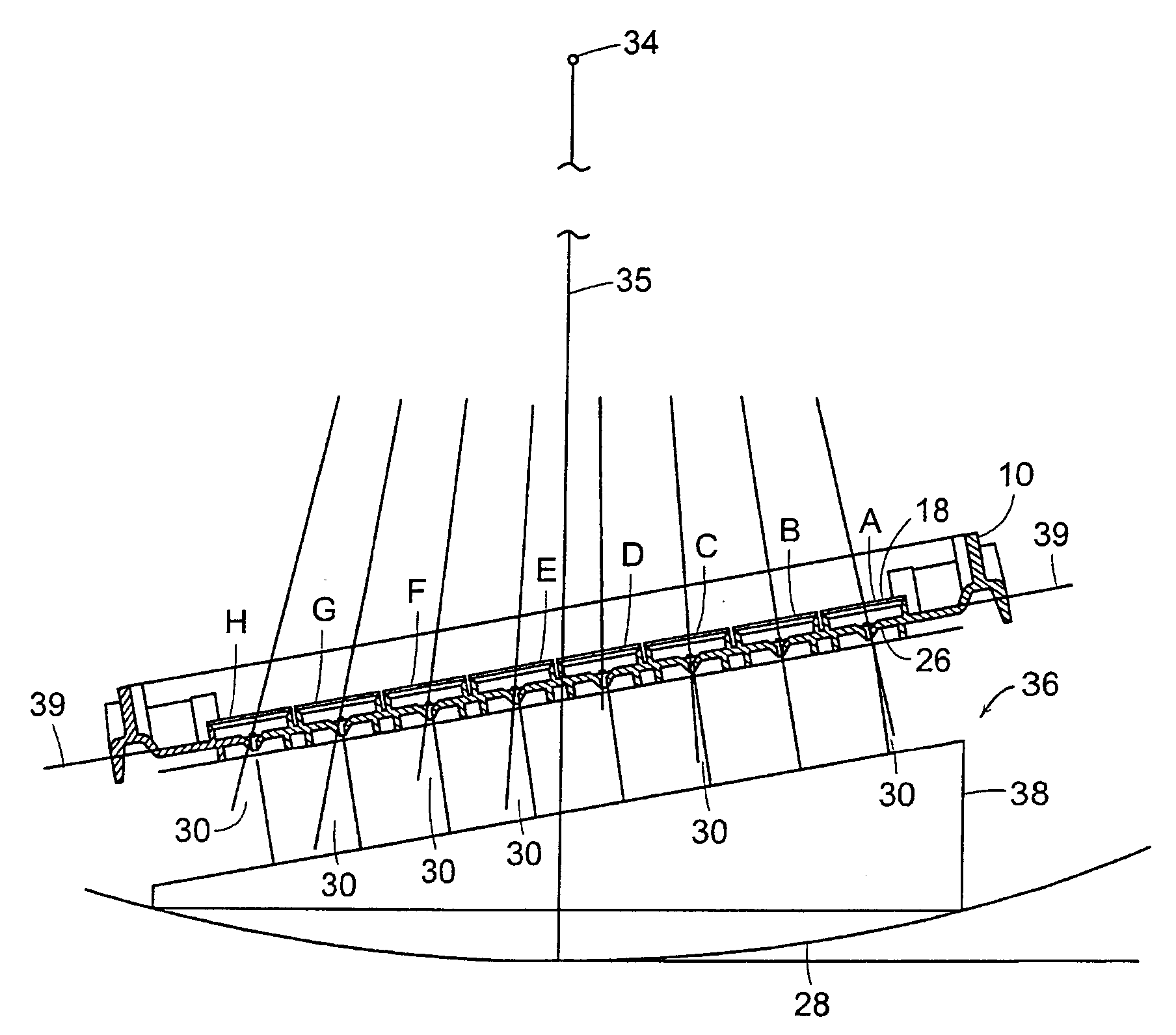
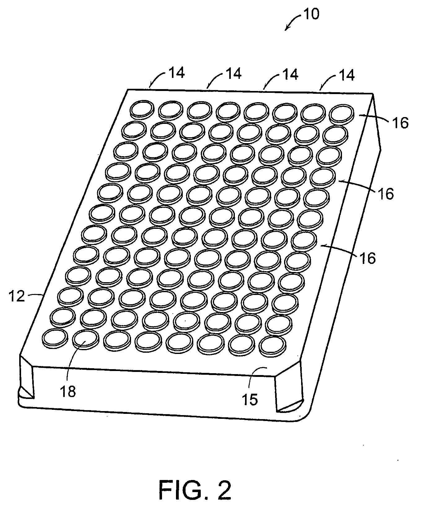
[0031]FIG. 2 illustrates a filtration well plate given generally as 10. The filtration well plate 10 has a housing 12 containing a plurality of wells 18. Typically, 2, 6, 8, 12, 24, 48, 96 or 384 wells are in each plate 10. The wells 18 can form an array having rows 14 and columns 16. In a 96 well plate, the rows 14 of wells 18 can have a total of eight rows, labeled A-H, and the columns 16 of wells 18 can have a total of twelve columns, labeled 1-12. A filtration well plate having these dimensions provides a total of ninety-six individual wells 18 which can form an array within a single plane. The face of the well plate 10 forms a major plane 15 of the plate 10. The filtration well plate 10 is positioned on top of a collection well plate 19, which allows collection of a filtered fluid, as shown in FIG. 3.

[0032]FIG. 4 illustrates a single well 18. The well 18 includes a storage chamber 20 on top of a filtrate collection chamber 22. A connector 24 can be located between the storage ...


PUM

PropertyMeasurementUnit
angleaaaaaaaaaa
membrane angleaaaaaaaaaa
angleaaaaaaaaaa

Abstract

A fluid filtering device includes a plurality of filtering wells and an angling mechanism which adjusts the angle of the membranes within the filtering wells relative to a line of a centrifuge where the line is perpendicular to the axis of rotation of a centrifuge and passes through the center of a major plane of the filtering device. The angling mechanism can include a wedge located between the center of rotation of a centrifuge and a swinging bucket of the centrifuge. The angling mechanism can also be located within each filtering well and can provide individually specified angles for each membrane, relative to the line of the centrifuge.

Description

RELATED APPLICATION [0001] This application is a divisional of U.S. application Ser. No. 09 / 637,403, filed Aug. 11, 2000. The entire teachings of the above application are incorporated herein by reference.BACKGROUND OF THE INVENTION [0002] Multiple well filtration plates such as ninety-six well plates containing the standard eight by twelve array are commonly used to filter fluids using either vacuum or centrifugal force for a variety of applications. Ultrafiltration membranes typically require more force than generated by vacuum to filter a fluid and have to be run using centrifugation or pressure. Centrifuges adapted with rotors and carriers for the ninety-six well microtiter plates are very common laboratory equipment and therefore frequently used to generate the forces required to drive filtration. Viscous, high protein containing serum or plasma is one of the fluids requiring ultrafiltration. In one application, protein free filtrate from serum is required for drug analysis whi...

Claims


Application Information

Patent Timeline
Patent Type & Authority Applications(United States)
IPC IPC(8): B01D61/18B01D61/20B01D63/16B01L3/00B04B5/04
CPCB01D61/18B01D61/20B01D63/16Y10T436/255B01L2300/0829B01L2400/0409B04B5/0421B01L3/50255
Inventor PITT, ALDO M.GUTIERREZ, SARA D.ZERMANI, THOMAS G.BUSNACH, JEFFREYRANERI, JOSEPH J.GROVES, JAMES C.
Owner MILLIPORE CORP
Why Eureka
Try Eureka