Imaging device

a technology of image artifacts and detectors, which is applied in the direction of radio frequency controlled devices, instruments, television systems, etc., can solve the problems of rapid fluctuations and inability to use digital data generated by new-style flat-panel detectors for diagnostic purposes in raw state, and achieve the effect of reliable compensation of image artifacts

Inactive Publication Date: 2005-07-28
SIEMENS HEALTHCARE GMBH
View PDF9 Cites 42 Cited by
  • Summary
  • Abstract
  • Description
  • Claims
  • Application Information

AI Technical Summary

Benefits of technology

[0022] In a further preferred embodiment the evaluation unit records—in conjunction with the performance of an offset acquisition operation—the temperature of the detector. If the subsequent monitoring indicates that the temperature of the detector has exceeded a defined threshold value, the evaluation unit requests the recording of a new offset image. Since the temperature of the detector significantly affects the offset of the pixels in the detector, a reliable compensation of the image artifacts may be achieved in this way.

Problems solved by technology

The digital data generated with the new-style flat-panel detectors cannot be used for diagnostic purposes in its raw state, since the optical and electrical properties of the individual detector elements of the flat-panel detectors, the pixels, can vary greatly.
The leakage currents may result in rapid fluctuations since the detector temperature—for its part—depends on the ambient temperature and on temperature fluctuations occurring during operation due to power dissipation.

Method used


Image

  • Imaging device
  • Imaging device
  • Imaging device

Examples


Embodiment Construction

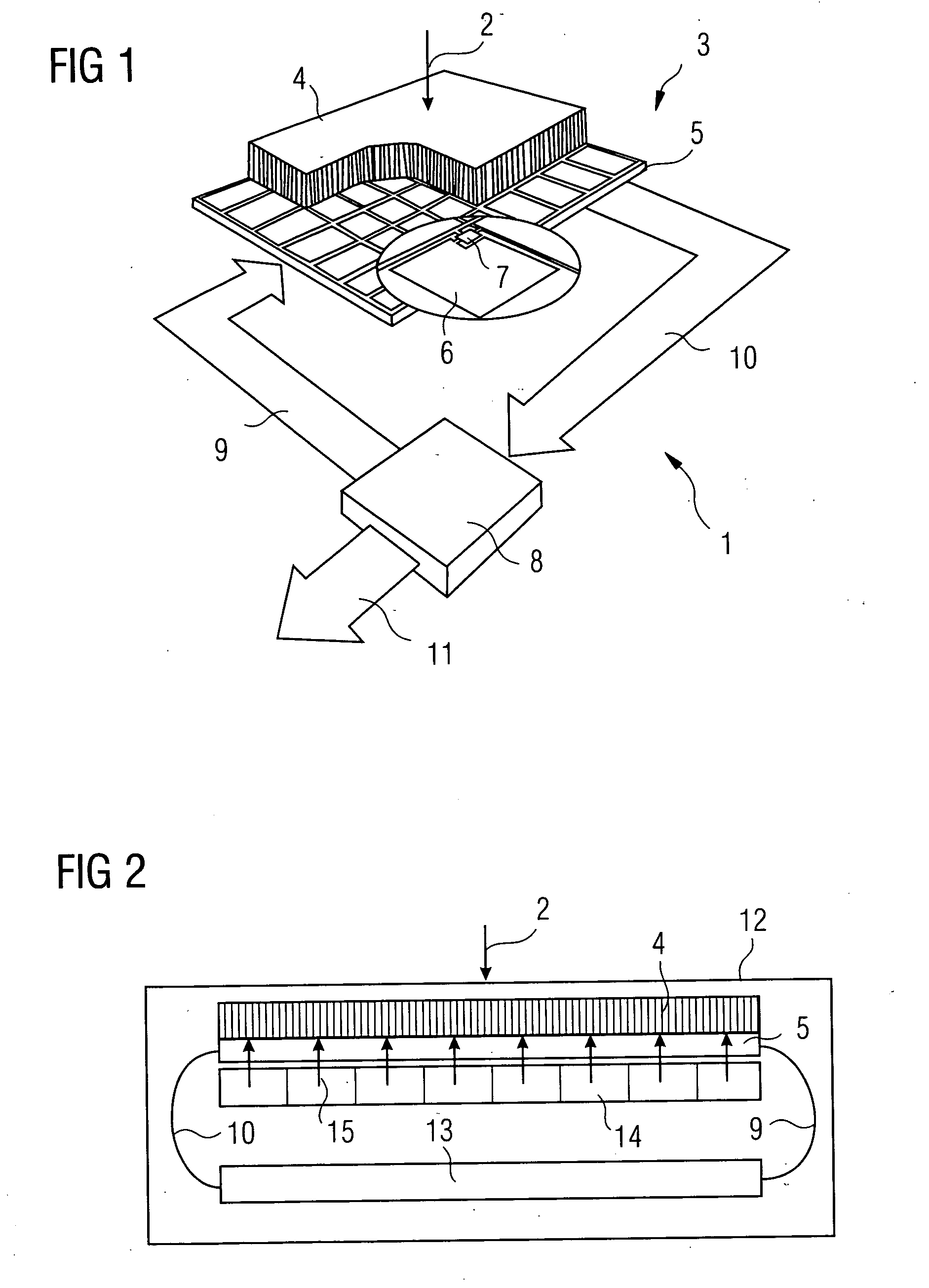
[0029]FIG. 1 shows an imaging device 1, which is p art of an x-ray device and which incorporates an x-ray source (not shown in FIG. 1) for generating x-rays 2. The x-rays 2 fall on a flat-panel detector 3 after passing through an object to be radiographed. The flat-panel detector 3 typically measures about 30 cm by 30 cm. The flat-panel detector 3 incorporates a scintillator 4, which is manufactured—for example—from CsI. Below the scintillator 4, there is an active matrix 5, which is normally manufactured on the basis of amorphous silicon. A field of photodiodes is formed on the active matrix 5. In the photodiodes 6, the light generated in the scintillator 4 via the respective photodiode 6 is absorbed. During this absorption, electron-hole pairs are generated which migrate in turn to the anode and cathode of the respective photodiode 6. The charge thus generated is stored in the respective photodiode 6 until said photodiode 6 is read out with the help of an active switching element ...


PUM


Abstract

In order to monitor an imaging device for x-ray machines it is proposed that reference system data (19) be recorded in conjunction with a calibration (16) or offset acquisition and that current comparison system data (20) be recorded later in the operating process, and that the performance of a new calibration (16) or the recording of a new offset image be triggered if the current comparison system data (20) deviates from the reference system data (19) by a predefined amount.

Description

CROSS REFERENCE TO RELATED APPLICATIONS [0001] This application claims priority to the German application No. 10 2004 003 881.3, filed Jan. 26, 2004 which is incorporated by reference herein in its entirety. FIELD OF INVENTION [0002] The invention relates to an imaging device having a detector for recording high-energy images with the help of high-energy photons and having an evaluation unit which records the status of the system parameters describing the imaging device. BACKGROUND OF INVENTION [0003] Imaging devices of this type are generally known in the form of x-ray machines. X-ray machines for digital X-ray imaging are currently being developed. The new-style x-ray machines for digital x-ray imaging use so-called flat-panel detectors (among other things) that can be classified as flat-panel detectors with direct conversion and flat-panel detectors with indirect conversion. [0004] Flat-panel detectors with indirect conversion have a scintillator extended over the surface, which ...

Claims


Application Information

Patent Timeline
Patent Type & Authority Applications(United States)
IPC IPC(8): A61B6/00G01T1/17G01T1/20G01T1/29G06K1/00H04N5/217H04N5/32H04N5/359H04N5/361H04N5/367
CPCA61B6/583A61B6/585H04N5/3675H04N5/3597H04N5/361H04N5/32H04N25/626H04N25/683H04N25/63
Inventor SPAHN, MARTIN
Owner SIEMENS HEALTHCARE GMBH
Why Eureka
Try Eureka