Wavelength extension for backthinned silicon image arrays

Active Publication Date: 2005-07-28
EOTECH LLC
View PDF14 Cites 25 Cited by
  • Summary
  • Abstract
  • Description
  • Claims
  • Application Information

AI Technical Summary

Benefits of technology

[0005] It is a goal of this invention to achieve extended wavelength results with no loss in low light level performance or image quality in a camera system based on a back-thinned silicon focal plane. The primary targeted application of these back-thinned silicon focal planes is their use as anodes within an electron bombarded night vision sensor. Consequently, the approach detailed in U.S. Pat. No. 4,891,507 is not used. In order to achieve the stated goals, the preferred embodiment places the up-conversion material on the surface opposite that of the incoming light, typically between a back-thinned sensor and it's support substrate. Althoug

Problems solved by technology

The placement of the up-converter at the supported surface of the back-thinned sensor makes use of a “charged” up-conver

Method used


Image

  • Wavelength extension for backthinned silicon image arrays
  • Wavelength extension for backthinned silicon image arrays
  • Wavelength extension for backthinned silicon image arrays

Examples


Example

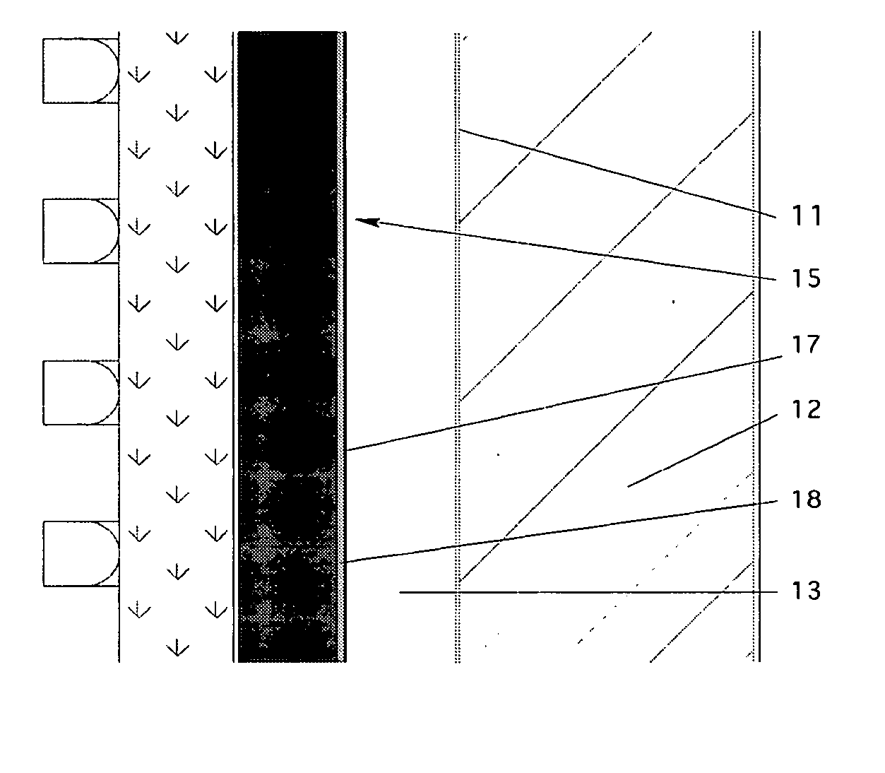
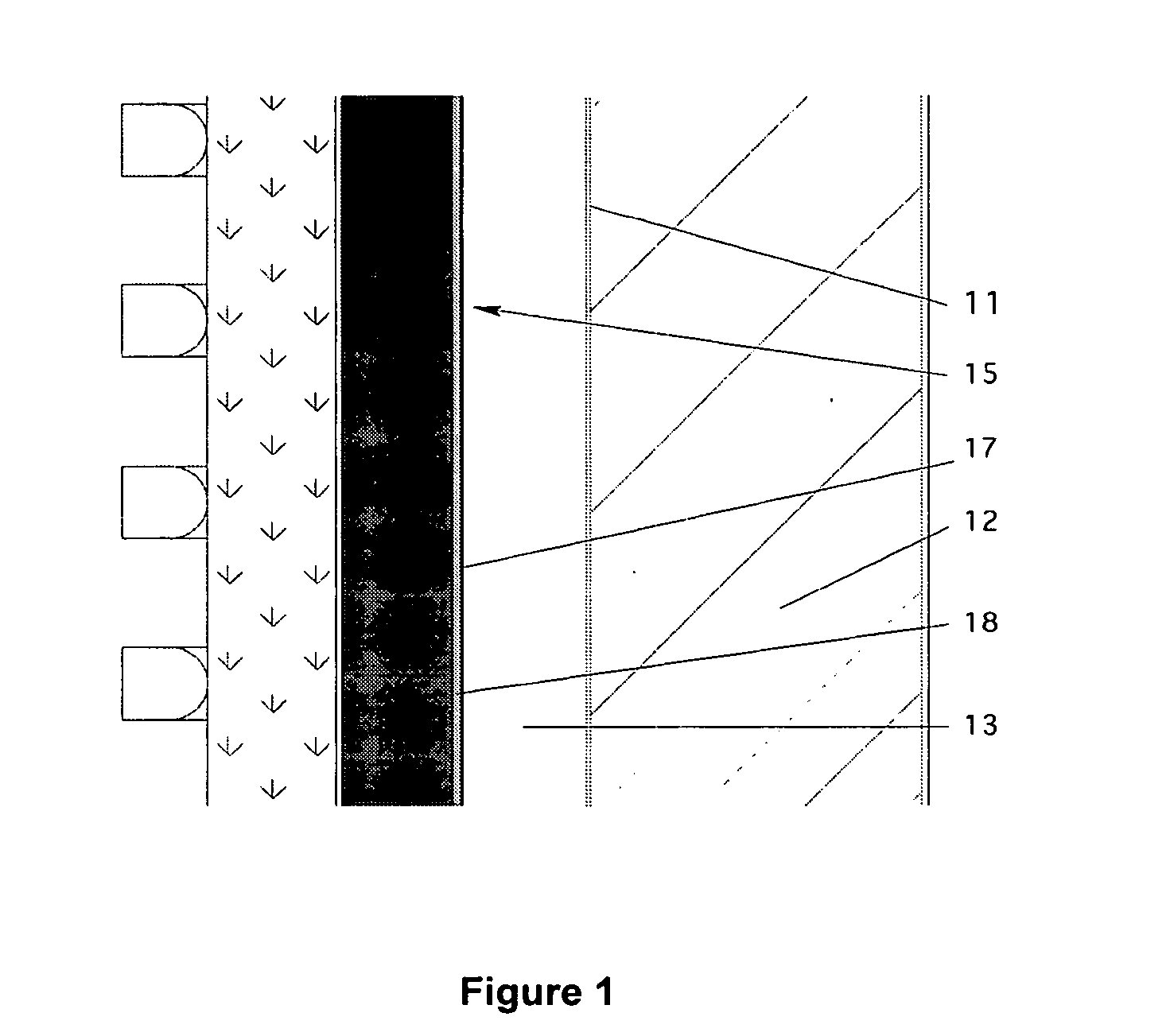
[0016] Referring now to FIG. 1, there is illustrated a CMOS sensor in accordance with this invention in position in a structure in which the back-thinned CMOS is exposed to electron bombardment. In this FIG. 11 represents a photocathode which in the preferred embodiment is a GaAs layer positioned on sensor window 12 which may comprise a transparent glass layer. Sensor window 12 represents the outer wall of the device illustrated. A vacuum separation 13 is between photocathode 11 and back-thinned surface 17 of silicon material of the CMOS imager 15. The back-thinned surface 17 comprises one of the outer surfaces of the CMOS sensor 15. Positioned between or under the back-thinned silicon layer 17 of sensor 15 and the remainder of the supporting assembly of sensor 15 is an up-conversion material or layer 18.

[0017] One specific goal of the detector is to be able to allow the detection of aiming lights. Aiming lights that fall between 1100 and 2000 nm would normally be invisible to both...


PUM


Abstract

There is described a back thinned sensor in which a material is added on the front surface to extend the wavelength of the sensor into wavelengths it normally does not reach. In the preferred embodiment, the back-thinned layer comprises silicon and is the base for a CMOS device or a CCD. The photocathode in a night vision device comprises in the preferred unit GaAs.

Description

BACKGROUND OF THE INVENTION [0001] Back-thinned silicon arrays are used in various photographic systems. For example back-thinned silicon CCDs are used today in various camera systems as is described for example in U.S. Pat. Nos. 4,760,031, 4,822,748 and 4,687,922 and back-thinned silicon CMOS structures are being used with particular success in various night vision systems. One such application is the use of such an array in cameras that reproduce images using bombardment by electrons of pixel sensors. This system is described for example in U.S. Pat. Nos. 6,285,018, 6,657,178 and 6,507,147. [0002] Cameras to create images based on electron bombardment represent, among other things, a new generation of high performance night vision video sensors. Their light-weight and compact size match the requirements for head mounted night vision systems. Such cameras have an effective spectral response that results from the sum of both the responses of their photocathode and the underlying pix...

Claims


Application Information

Patent Timeline
IPC IPC(8): H01L21/00H01L27/146H01L27/148H01L29/732H01L31/00H01L31/072
CPCH01L27/14643H01L27/14806H01L27/14649
Inventor COSTELLO, KENNETH A.
Owner EOTECH LLC
Why Eureka
Try Eureka