Bandpass filter for differential signal, and multifrequency antenna provided with same
- Summary
- Abstract
- Description
- Claims
- Application Information
AI Technical Summary
Benefits of technology
Problems solved by technology
Method used
Image
Examples
first embodiment
[0023] A bandpass filter for a differential signal relating to the first embodiment of the invention will now be described with reference to the drawings. First of all, the structure of this bandpass filter for a differential signal will be described, and then theoretical operation of this bandpass filter for a differential signal and its characteristics will be described.
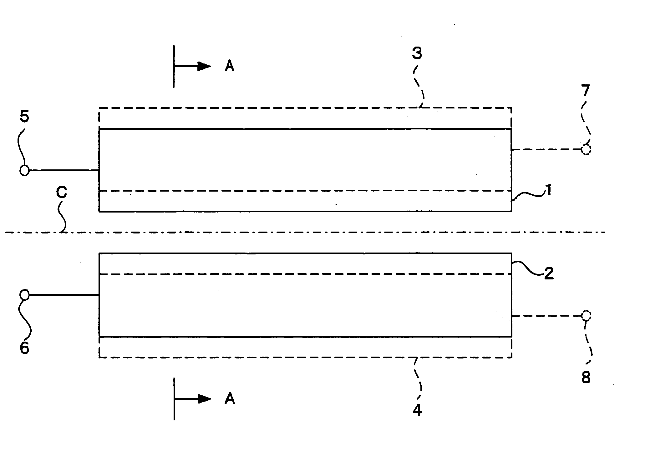
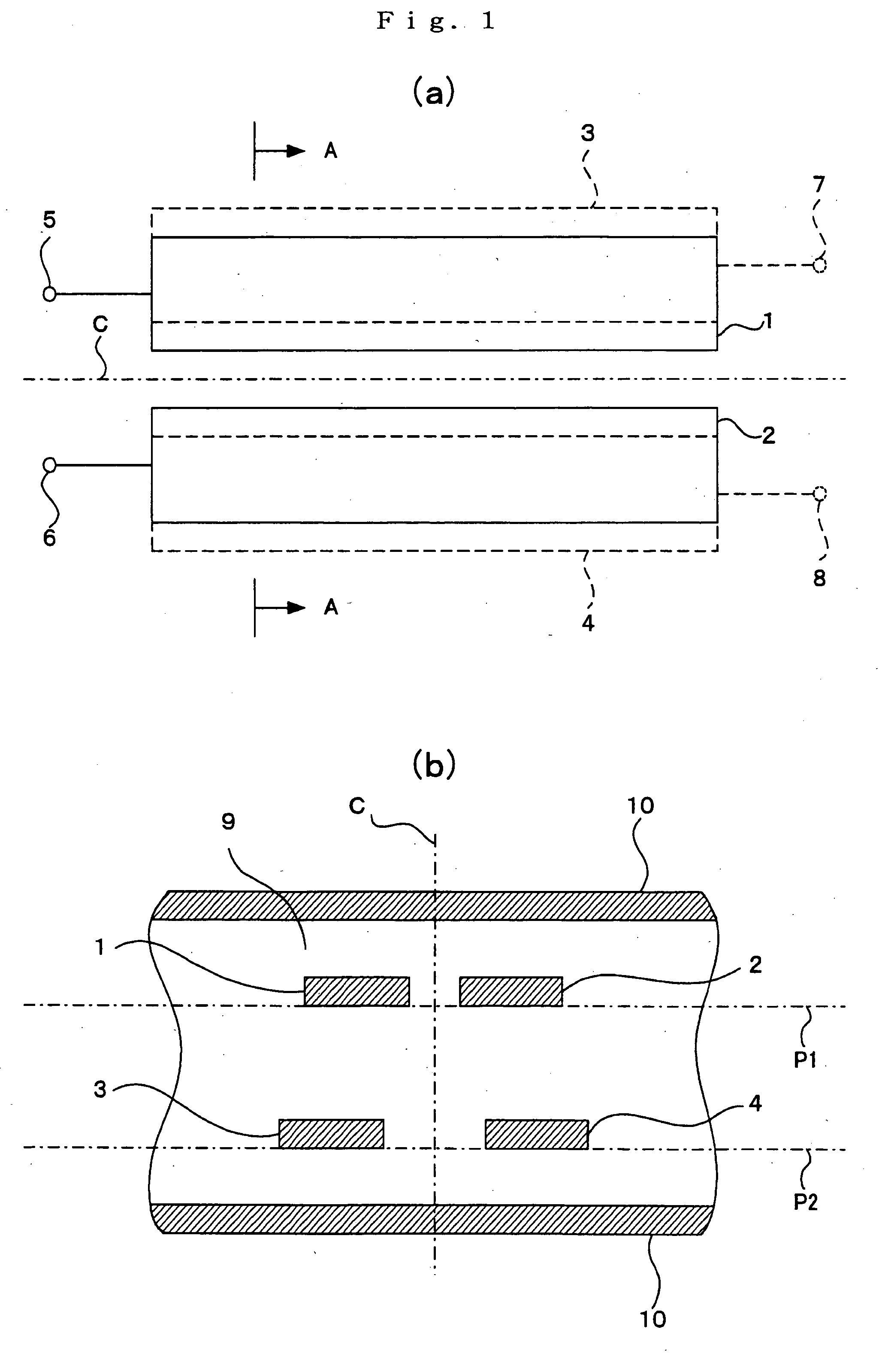
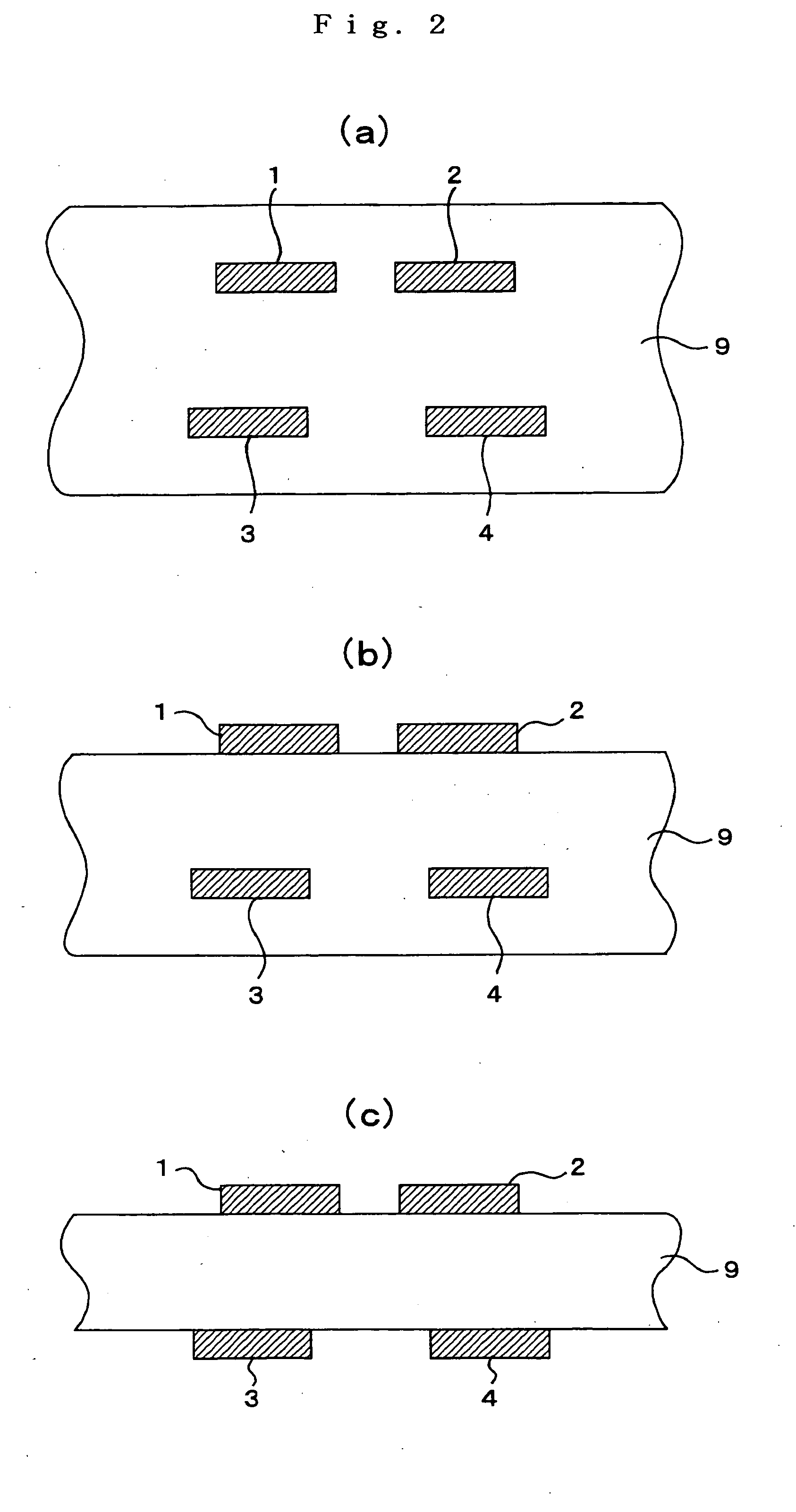
[0024] The structure of the filter relating to the first embodiment of the invention is shown in FIG. 1(a) and FIG. 1(b). FIG. 1(a) is a plan view of the filter, while FIG. 1(b) is a cross sections looking in the direction of arrows A-A in the plan view (arrow A-A cross sectional view). In these drawings, reference numeral 1 is a first line, 2 is a second line, 3 is a third line, and 4 is a fourth line. Reference numeral 5 is an input / output end of the first line 1, while 6 is an input / output end of the second line 2. The input / output ends 5, 6 together form a first differential input / output end. Ends at the oppos...
second embodiment
of the Invention
[0065] UWB communication systems suppress interference with other wireless systems by having small transmission power. However, 5 GHz band wireless LAN systems used between individuals similarly are often in the same room, and in this case, it is confirmed that interference arises. In order to avoid this, a 5-6 GHz band used in a wireless LAN was evaluated so that there was no radio wave output in the UWB. The second embodiment of the invention is used in an intermediate manner in this way, and a band stop filter for steeply cutting off some frequencies within a band of a wideband pass filter of the first embodiment of the invention, and minimizing effects on other bands, is provided in the wideband pass filter of the first embodiment.
[0066]FIG. 5 is a plan view of a wideband filter for a differential signal fitted with a band stop filter of the second embodiment of the invention. In FIG. 5, the same reference numerals are attached to sections that are the same as i...
third embodiment
the Invention
[0070] A filter of the third embodiment of the invention has two wideband bandpass filters of the first embodiment of the invention cascade-connected, and is provided with a band stop filter for cutting off some frequencies within that band steeply while keeping the effect on other bands to a minimum connected to the cascade connection point. The filter of the third embodiment of the invention has a different structure to embodiments 1 and 2 of the invention.
[0071]FIG. 6 is a plan view of the filter relating to the third embodiment of the invention. Reference numerals 11 and 12 are a first line and a second line arranged on a first surface. The first line 11 and second line 12 have respective line lengths equivalent to about a quarter wavelength of a center frequency of a used band (0.25 wavelengths, 0.75 wavelengths, 1.25 wavelengths, 1.75 wavelengths etc.) but are actually slightly shorter than a quarter wavelength (for example, {fraction (1 / 100)} of wavelength (0.01...
PUM
 Abstract
Description
Claims
Application Information
 - R&D
- Intellectual Property
- Life Sciences
- Materials
- Tech Scout
- Unparalleled Data Quality
- Higher Quality Content
- 60% Fewer Hallucinations
Browse by: Latest US Patents, China's latest patents, Technical Efficacy Thesaurus, Application Domain, Technology Topic, Popular Technical Reports.
© 2025 PatSnap. All rights reserved.Legal|Privacy policy|Modern Slavery Act Transparency Statement|Sitemap|About US| Contact US: help@patsnap.com


