
Digital video surveillance

a digital video and surveillance technology, applied in the field of digital video surveillance, can solve the problems of not providing continuous monitoring, if not impossible, and difficult expansion of the system once it is wired,

Inactive Publication Date: 2005-07-28
INTERGRAPH SOFTWARE TECH
View PDF25 Cites 52 Cited by
  • Summary
  • Abstract
  • Description
  • Claims
  • Application Information

AI Technical Summary

Benefits of technology

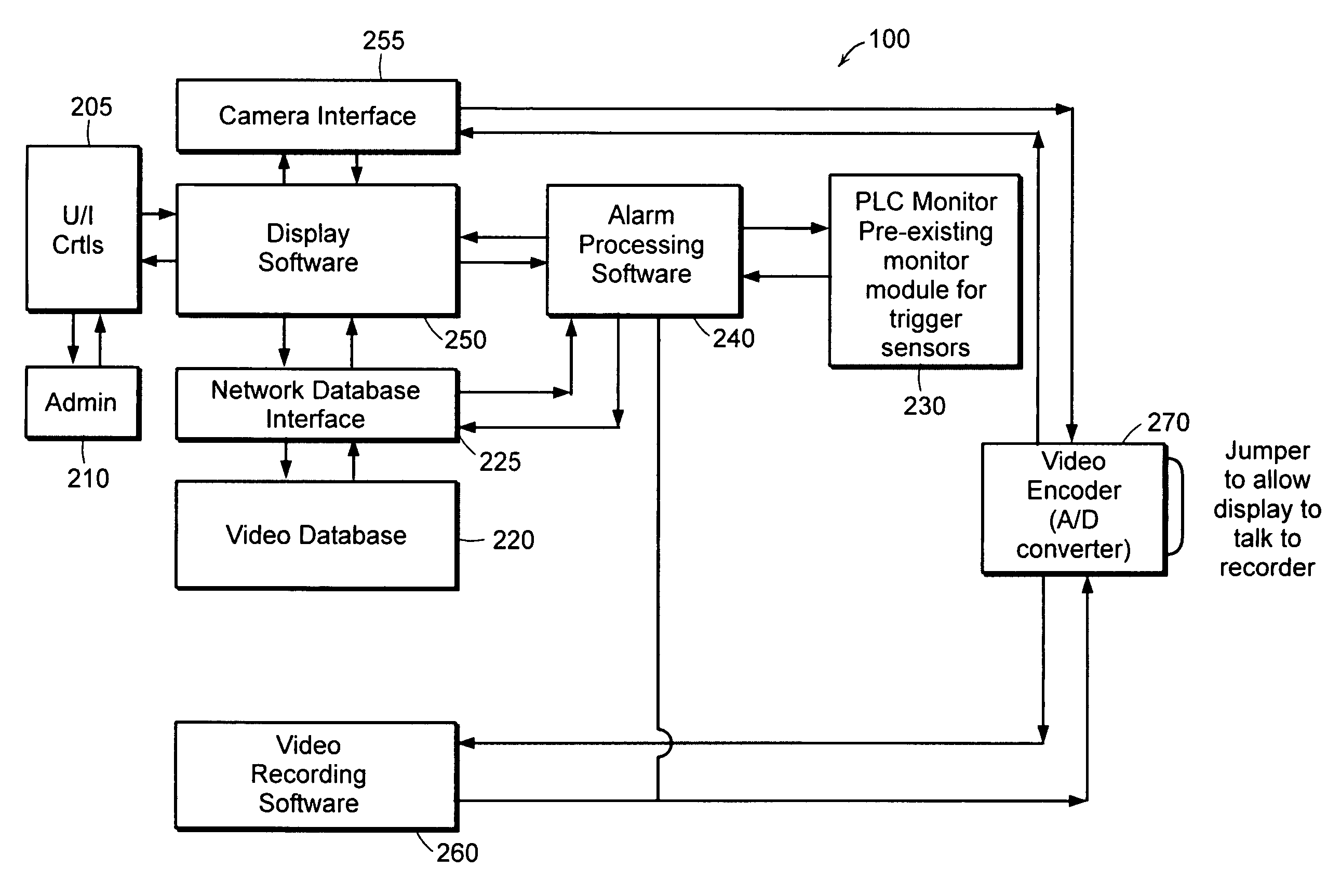
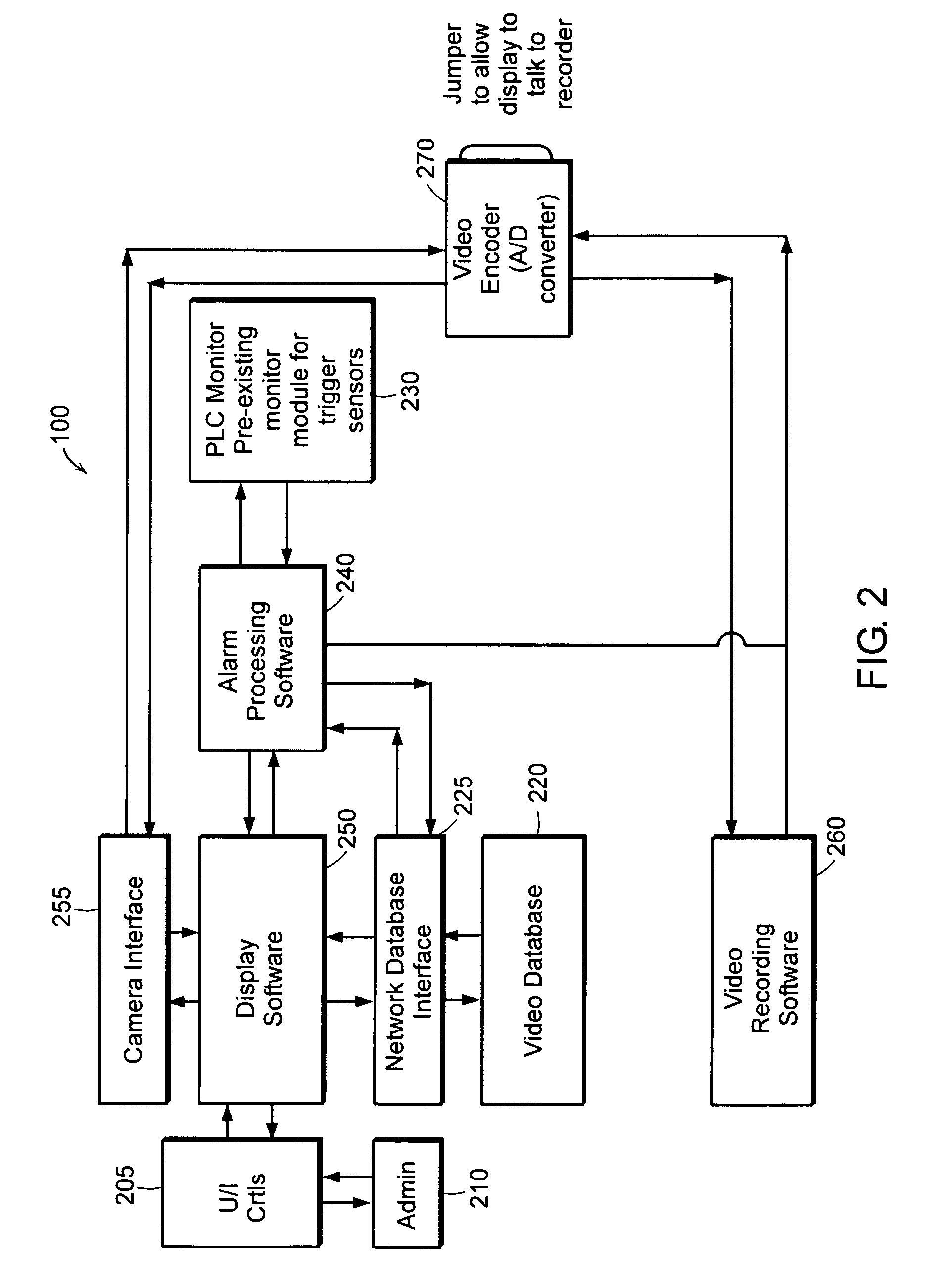
[0009] The system is modular and may be distributed among multiple servers. The system may employ DCOM or another distributed architecture so that the various modules can run on separate machines over an existing computer network. This reduces the need for wiring and can provide added access control. Thus each module includes a network component and the modules may be located at different remote locations. This modular approach also allows the system to continue to function even if one of the modules becomes corrupted or fails. Additionally, the system can evaluate the amount of data that is being transmitted through a network and can give priority to image data that is associated with a camera that is having an alarm condition.

Problems solved by technology

Having to rewire all of the cameras and all of the trigger sensors in a surveillance system can be extremely time consuming and costly especially on large scale systems.
Further, expansion of the system once it is wired is difficult, if not impossible.
Additionally, prior art surveillance systems do not provide for continuous monitoring such that the system will automatically shift between a normal condition state and a configurable alarm condition state wherein images from different cameras are recorded and stored depending upon the state.
Still further, the prior art systems do not allow the user to define the alarm conditions which will trigger the storage of image information.
Prior art systems may include trigger sensors, but do not allow the user to define the threshold parameters that will cause the trigger sensors to set off an alarm.
Nor do these prior art systems allow the user to combine different trigger sensors and different parameters for the trigger sensors in combination in order to set an alarm condition.
Further, users of the prior art systems cannot create an alarm condition by selecting trigger sensors and selecting parameters for the trigger sensors.
Additionally, prior art video surveillance systems are not modular and are not designed for a distributed architecture.
For example, if the video display section of a prior art video surveillance system fails then the system would also fail to record images.

Method used


Image

  • Digital video surveillance
  • Digital video surveillance
  • Digital video surveillance

Examples


Embodiment Construction

[0022] In the following disclosure and the appended claims the term “module” shall apply to both software embodiments and hardware embodiments, as well as, combinations of software and hardware, unless the context indicates otherwise.

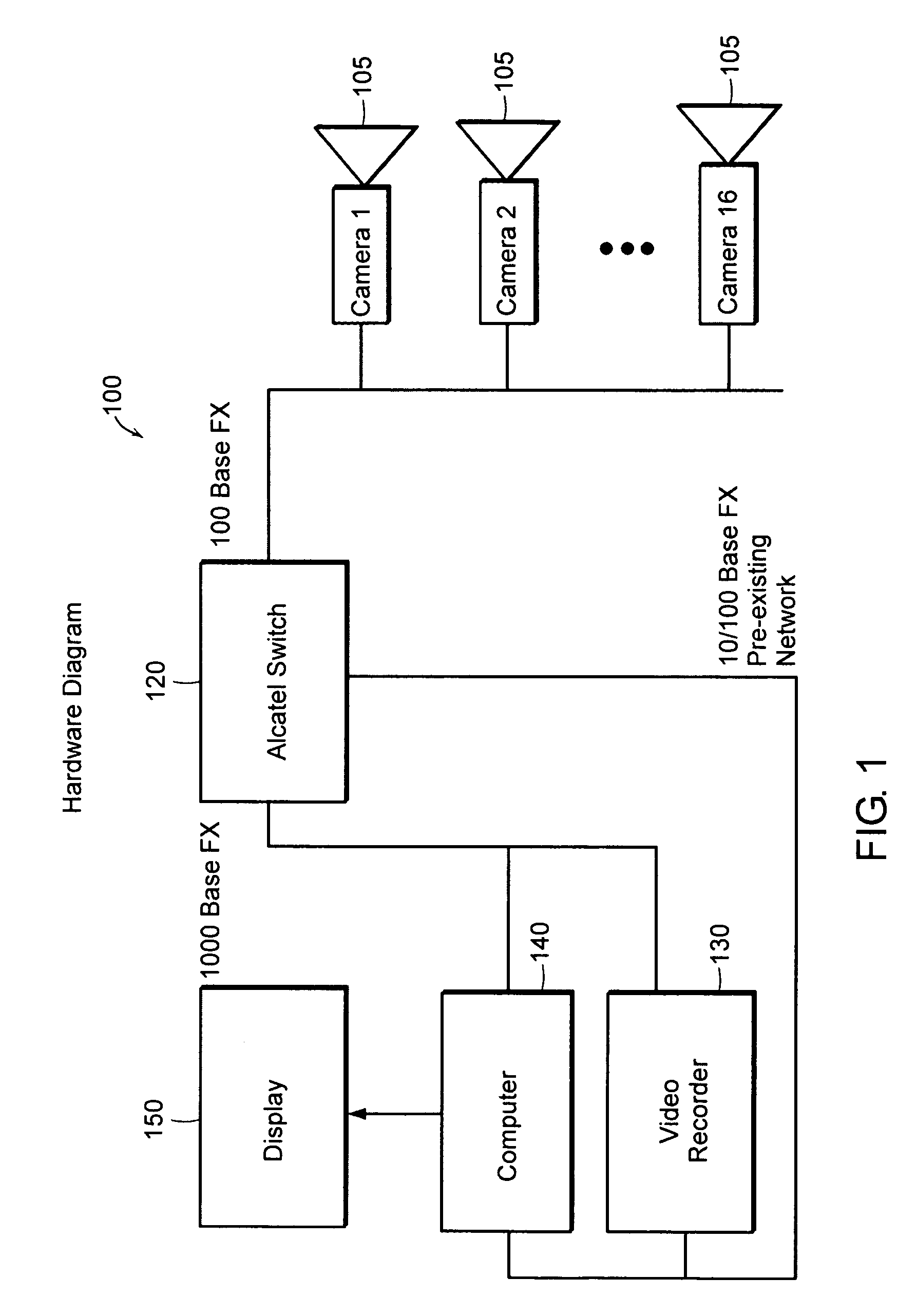
[0023]FIG. 1 is block diagram showing the hardware employed in one embodiment of the digital video surveillance system 100. The digital video surveillance system 100 includes one or more cameras 105 that are networked together and that incorporate one or more trigger sensors (not shown). The digital video surveillance system 100 may be combined with a legacy system without having to rewire the network or requiring new contacts for the trigger sensors. The pre-existing legacy network may be used. In exemplary FIG. 1, the system includes sixteen digital cameras 105 that are connected together over a 100 Base FX Ethernet / fiber network which is part of a legacy system. A multi-mode switch such as an Alcatel Omni Stack 6100 fiber switch 120 is employed for ...


PUM


Abstract

A control system for use with one or more video surveillance cameras forming a video surveillance system. The control system includes a video database module wherein a database entry includes at least one sensor condition defining an alarm state for each camera. Additionally, there is an alarm condition module that receives one or more sensor signals from one or more sensors associated with a camera and retrieves the sensor condition defining an alarm state for the camera. The alarm condition module outputs an alarm signal if the alarm condition module determines that the one or more sensor signals meets the one or more sensor conditions. The control system is modular and may be distributed in a network environment. The control system also monitors the network bandwidth and can adjust the throughput of digital data representing the digital images in order to avoid any bandwidth limitations.

Description

PRIORITY [0001] The present application claims priority from U.S. provisional application No. 60 / 520967 filed on Nov. 18, 2003 and having the title “Digital Video Surveillance.” This provisional application is incorporated by reference herein in its entirety.TECHNICAL FIELD AND BACKGROUND ART [0002] The present invention relates to digital video surveillance and more particularly to a digital video surveillance system capable of integrating with a pre-existing surveillance system without the need for rewiring the network connections. [0003] Prior art surveillance systems that are to be installed with legacy surveillance systems require complete network rewiring. This is especially true if the legacy system includes analog cameras and the new system is digital. In addition to rewiring all of the cameras, the sensors that trigger the cameras need to be rewired. Trigger sensors are sensors that coupled to a camera that indicate that an event has occurred. For example, a trigger sensor ...

Claims


Application Information

Patent Timeline
Patent Type & Authority Applications(United States)
IPC IPC(8): G08B1/00G08B13/196
CPCG08B13/19641G08B13/19656G08B13/1968G08B13/19697G08B13/19693G08B13/19695G08B13/19682
Inventor GRINDSTAFF, GENE A.WHITAKER, SHEILA G.
Owner INTERGRAPH SOFTWARE TECH
Learn More