
Methods of controlling transmission power levels in air interface channels

a transmission power level and air interface technology, applied in the field of wireless communications, can solve the problems of large delays and higher interference levels of lower qos traffic, and achieve the effect of reducing interference levels and high quality

Inactive Publication Date: 2005-07-28
KK TOSHIBA
View PDF7 Cites 84 Cited by
  • Summary
  • Abstract
  • Description
  • Claims
  • Application Information

AI Technical Summary

Benefits of technology

[0005] In general terms, the present invention provides a method of controlling a wireless network having at least one base station and one or more mobile stations each containing one or more radio transceivers, in which the power levels of channels allocated between a base station and a mobile station are dynamically varied in order to reduce the interference level on channels which are carrying traffic with a high quality of service level (QoS) requirement.
[0006] By controlling channel power levels, the network can optimise conditions for channels transmitting traffic (such as packets) requiring a high QoS. This may involve reducing the power levels on channels carrying traffic with a lower QoS requirement, which may, but need not, result in higher interference levels or larger delays for that lower QoS traffic. This enables more critical or sensitive data to be transmitted with greater accuracy, by providing a low interference channel when required, but without building into the network the need to maintain these low interference channels the whole time which would reduce capacity. Less critical or sensitive data can be transmitted using higher interference or lower QoS channels, thereby increasing the capacity of the network. If need be this data can be retransmitted as it is less sensitive to delays.

Problems solved by technology

This may involve reducing the power levels on channels carrying traffic with a lower QoS requirement, which may, but need not, result in higher interference levels or larger delays for that lower QoS traffic.

Method used


Image

  • Methods of controlling transmission power levels in air interface channels
  • Methods of controlling transmission power levels in air interface channels
  • Methods of controlling transmission power levels in air interface channels

Examples


Embodiment Construction

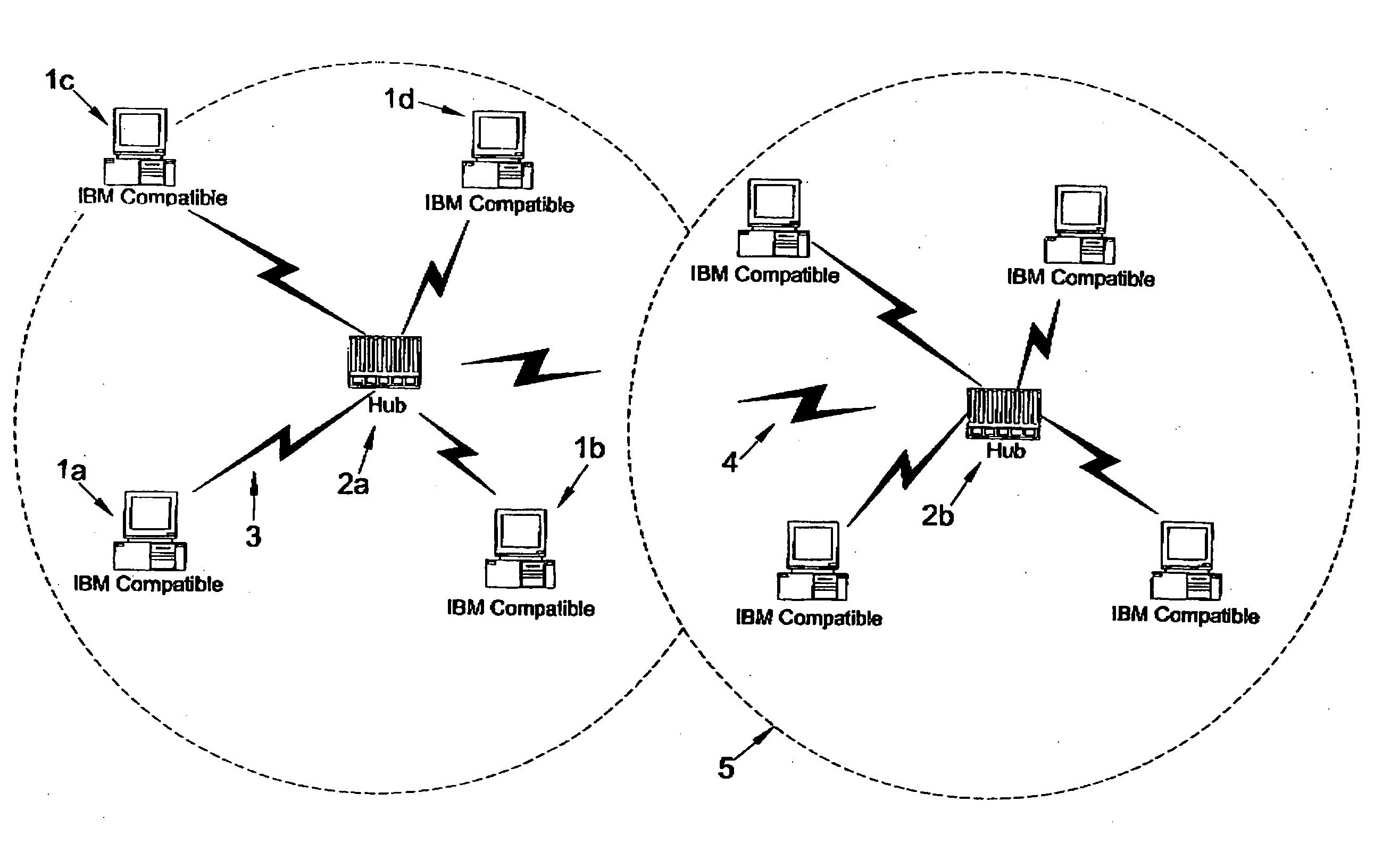
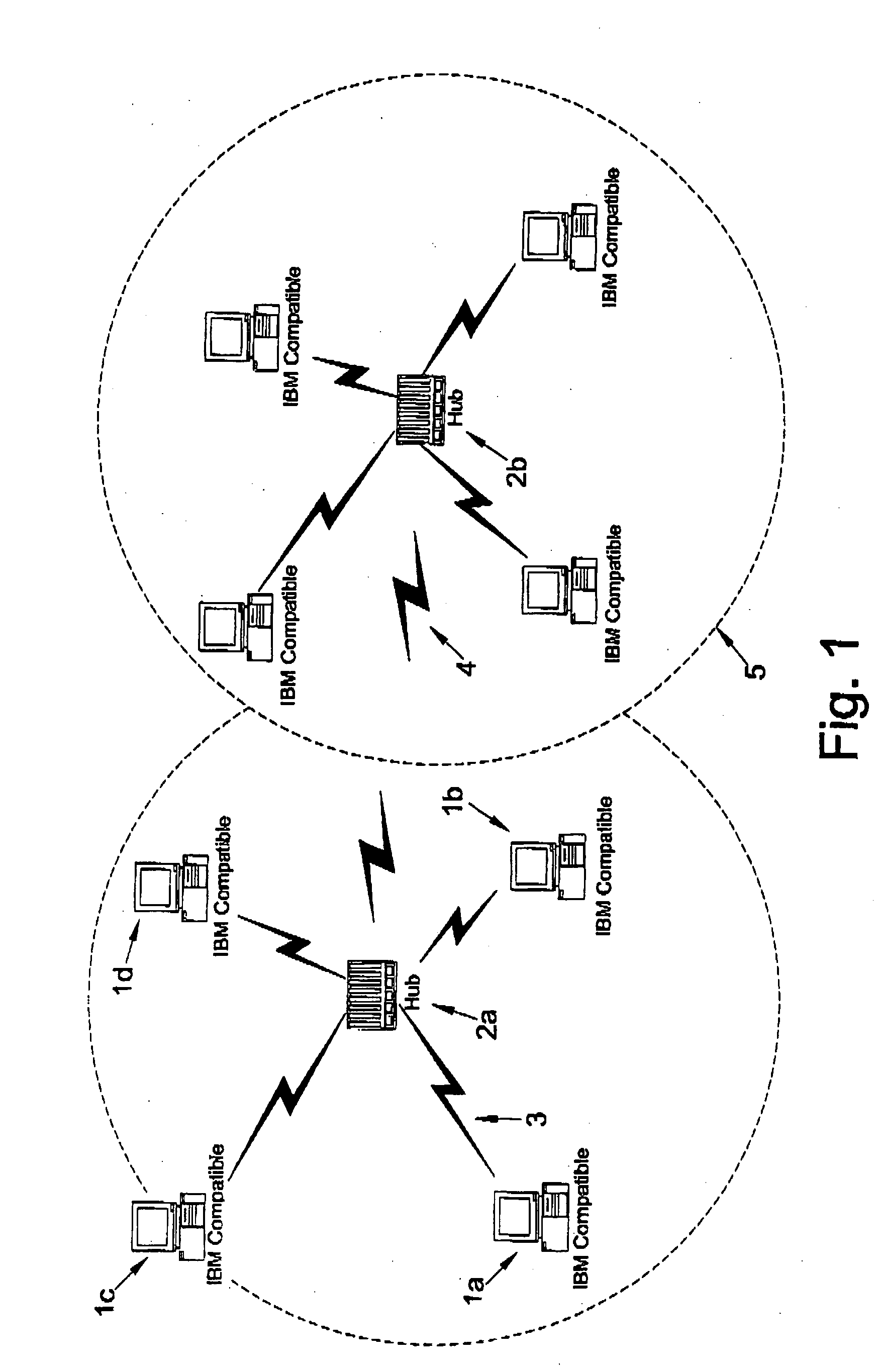
[0027]FIG. 1 shows an embodiment comprising a wireless network having one or more base stations or hubs 2 wirelessly coupled to a number of mobile stations 1. The network is arranged into one or more coverage areas 5. These coverage areas 5 might be PAN's (Personal Area Network) each comprising a number of collocated Bluetooth™ piconets each servicing a different mobile station 1 within the PAN. Alternatively the network might be a WLAN (Wireless Local Area Network) comprising adjacent or overlapping IEEE802.11 coverage areas 5 or a combination of PAN and WLAN. Wireless signals 3 couple each mobile station 1 to its corresponding base station 2. These signals 3 may also travel into adjacent areas 5 causing (especially) co-channel and adjacent channel interference (shown generally as 4).

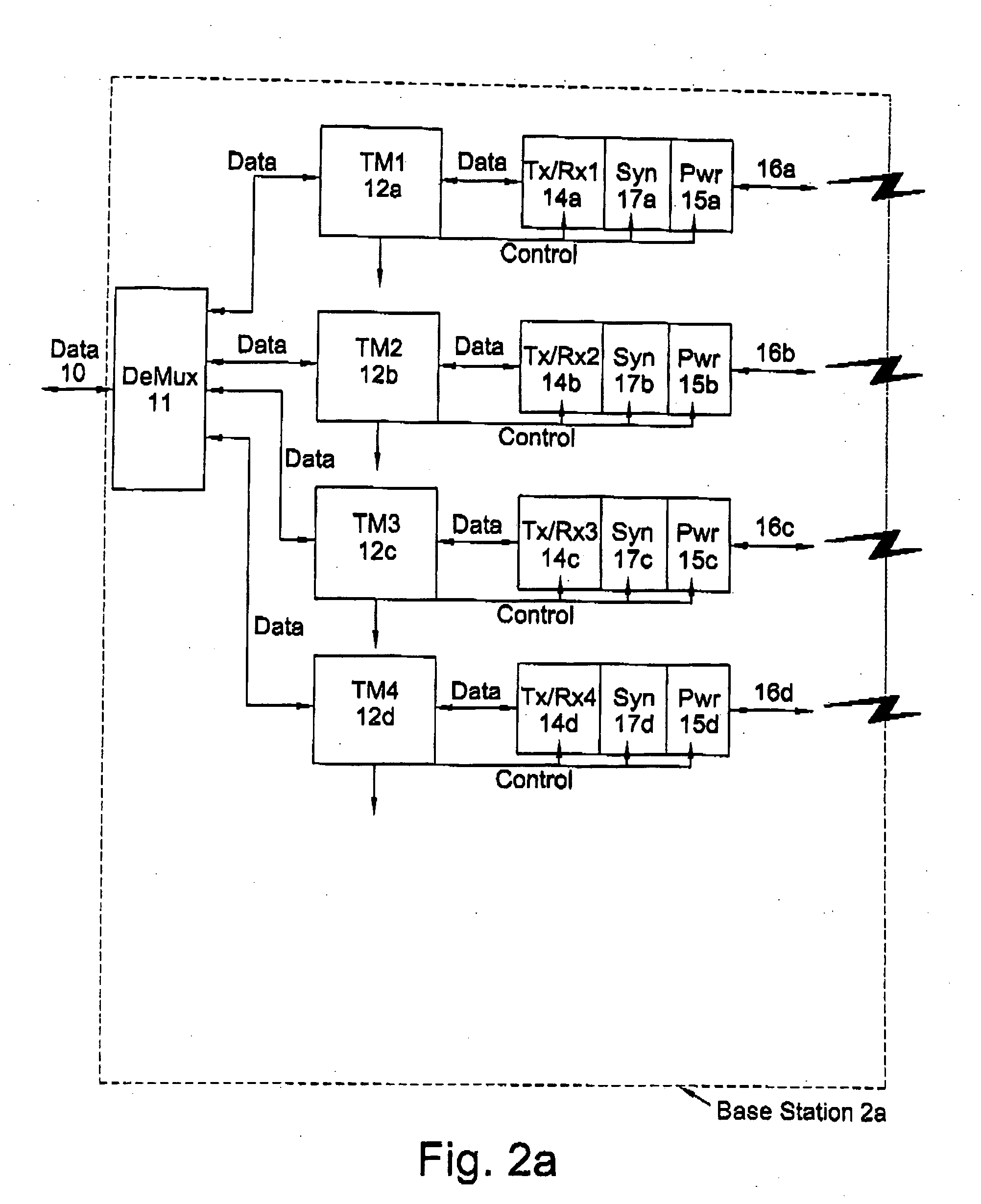
[0028]FIG. 2a is a schematic of a base station or access point 2a providing four air interface channel processing chains (shown generally as 16a, 16b, 16c, 16d) for communicating with mobile stations ...


PUM


Abstract

The present invention relates to wireless communications, and in particular although not exclusively, to networks of indoor collocated or overlapping wireless coverage areas especially those intended for operation in unlicensed spectrum such as the Industrial Scientific and Medical (ISM) bands. The present invention provides a method of controlling the transmission power associated with an air interface channel, the method comprising determining a quality of service measure for a signal to be transmitted on a second air interference channel; determining an interference measure corresponding to the interference on said second air interface channel which will be caused by transmissions on said first air interface channel; requesting the changing of the transmission power associated with the first air interface channel when the signal is to be transmitted on the second air interface channel, when the quality of service measure is above a predetermined value and when the interference measure is above a predetermined value for said quality of service value.

Description

FIELD OF THE INVENTION [0001] The present invention relates to wireless communications, and in particular although not exclusively, to networks of indoor collocated or overlapping wireless coverage areas especially those intended for operation in unlicensed spectrum such as the Industrial Scientific and Medical (ISM) bands. BACKGROUND OF THE INVENTION [0002] Collocated wireless coverage areas using different channels can still interfere with each other, adjacent channel suppression depends largely on the receiver implementation and transmitted spectral mask. Similarly, overlapping or adjacent wireless LAN coverage areas using uncoordinated spread spectrum mechanisms such as direct sequence or frequency hop spread spectrum also “intentionally” interfere with each other to a certain extent when the same or adjacent channels are used at the same time. Typically these channels are defined by frequency, (as used in frequency division multiple access) time slot (time division multiple acc...

Claims


Application Information

Patent Timeline
Patent Type & Authority Applications(United States)
IPC IPC(8): H04B1/04H04J13/00H04B1/713H04B7/005H04B7/26H04L12/28H04W52/24H04W52/26
CPCH04W52/265H04W52/243
Inventor FARNHAM, TIMOTHY DAVIDGAMBOA, GREGORY
Owner KK TOSHIBA
Learn More