[0009] The present invention seeks to provide new methods for ensuring the accurate use of CT or MRI scanned images in
surgical procedures, such as image-guided implantology. There is thus provided according to a first preferred embodiment of the present invention, a method whereby inherent distortions in the CT or
MRI imaging process, or distortions arising from excessive patient movement during the scan are corrected by means of a registration device inserted into the mouth of the patient at the time the scan is being performed. To this registration device is attached in a reproducible manner, a device known as a
distortion body which contains a set of fiducial markers disposed in a predetermined three-dimensional pattern, and whose location is registered on the images during the scanning. The exact positions of the fiducial markers are known with respect to each other, thus providing a three-dimensional reference against which the resulting images can be compared. This provides accurate spatial position information for correcting any
distortion present in the scanning and image-
processing procedure. Calculations are then performed for determining the
exact location of the fiducials in the CT data, the distortion between the three dimensional image obtained and the known true location of the fiducials, and for producing a correction function for use in interpreting the CT or MRI data such that it provides accurate positional data.
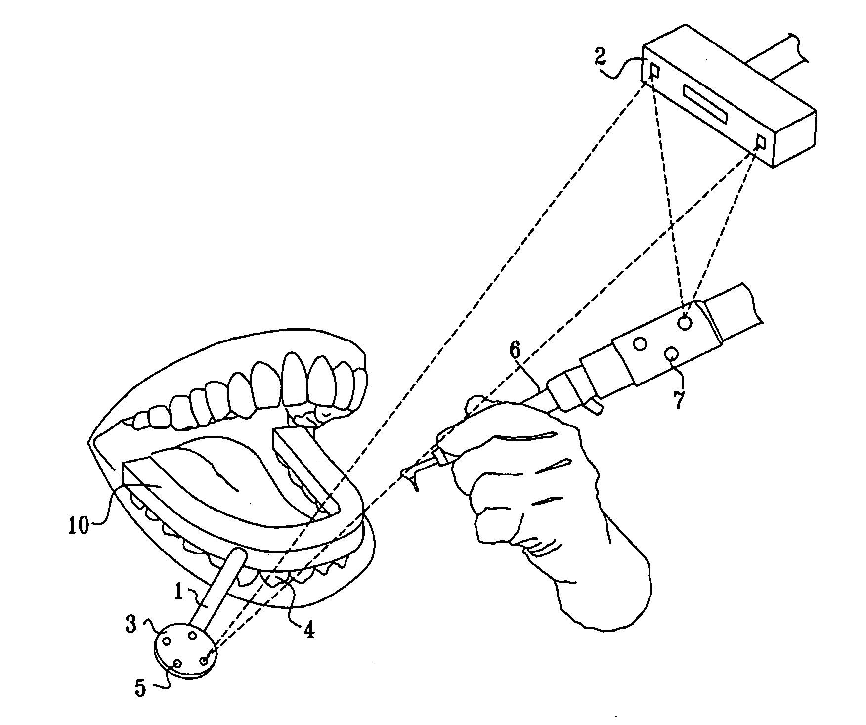
[0011] These images are then spatially and angularly related to the pre-operative images by means of a pre-
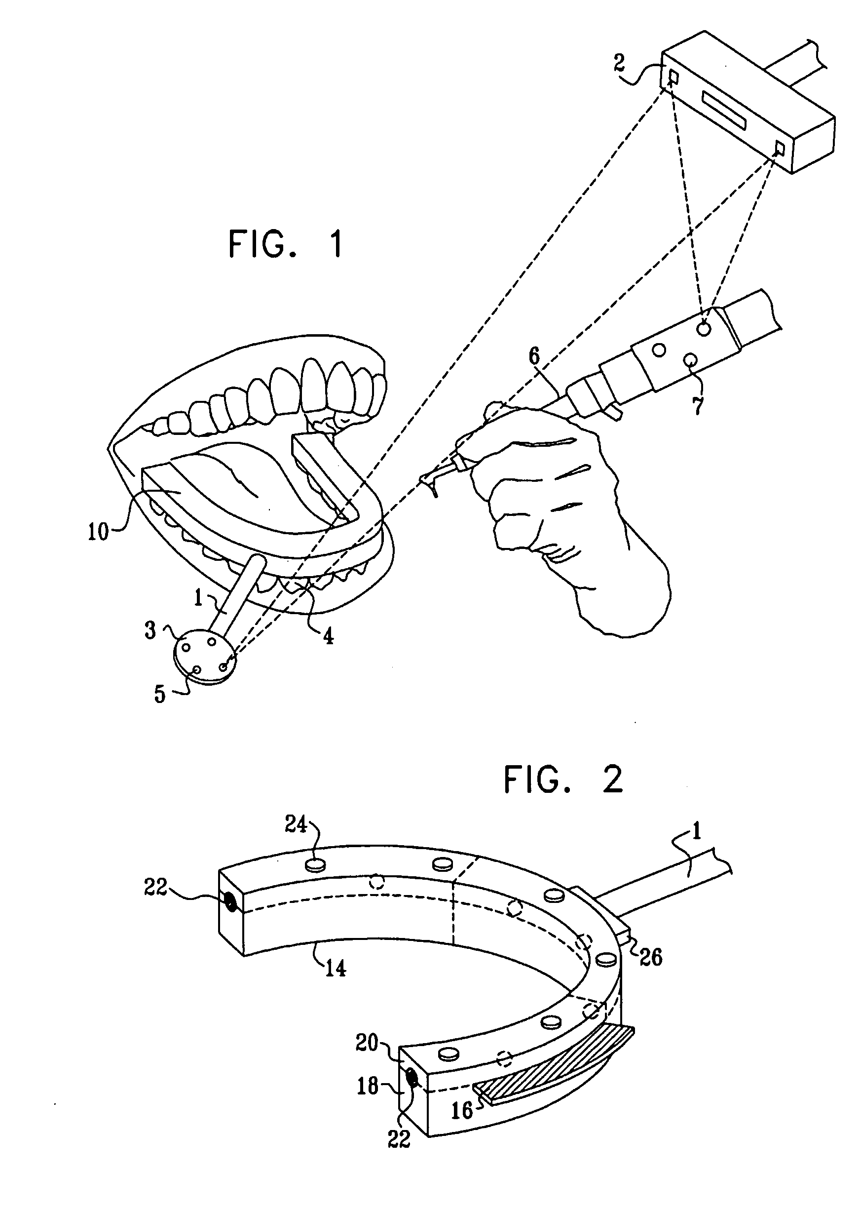
registration procedure performed according to another preferred embodiment of the present invention, in which a registration body containing fiduciary markers is inserted in a predefined manner into a registration jig, prior to commencement of any work on the patient. The position of the jig together with the inserted registration body is tracked by the
tracking system preferably by means of LED's mounted on the jig. Alternatively and preferably, the position of the registration body can be made known to the
tracking system by any other suitable positional determining device, such as by a manually held
stylus which is touched onto a reference point of the registration body, or even onto the fiducial markers themselves. Since the fiducial markers are the same ones as were incorporated in the scans previously made with the registration body in the patient's mouth, and thus bear a predefined and fixed spatial and angular relationship to the registration body, and the registration body to the patient's teeth, this correlation enables the virtual-world CT scans to be related to the functional world of the tooth and
drill as tracked in real time by the
system. Since this
registration procedure is performed outside of the patient's mouth, it has a number of advantages over prior art registration procedures performed involving the patient's jaw. In the first place, since the
registration procedure is performed outside of the patient's mouth, and without patient involvement, the accuracy and the reliability of the registration process is increased, as is the
patient comfort level, for the reasons stated hereinabove. Secondly, the registration process can be performed at any time before the procedure on the patient, and requires less skill and time than an intra-oral registration procedure, as in the prior art, with all the advantages thereby engendered.
[0013] There is also provided in accordance with another preferred embodiment of the present invention, a a method of compensating for distortions generated in an imaging process, comprising the steps of (a) providing a registration device with a plurality of markers disposed in a predetermined three-dimensional pattern, the markers being rendered visible in the imaging process, (b) producing a scanned image of an object of interest in the presence of the registration device, and (c) correcting the data of the scanned image such that the image of the markers accurately reproduces the predetermined three-dimensional pattern. The plurality of markers are preferably disposed either within the registration device, or within a body attached to the registration device. The above-described method can preferably be used for computerized
tomography or for
MRI imaging. Furthermore, the method can preferably be used when the object is at least part of a jaw of a subject, in which case the registration device is adapted to fit in a reproducible position in the at least part of the jaw.

