Method for manufacturing a composite material

a manufacturing method and composite material technology, applied in the field of composite material manufacturing methods, can solve the problems of difficult to predict the dimensions of the final product, difficult to obtain a proper “balance” between the individual components of the composite material, and difficult to achieve the effect of enhancing the e-modulus, improving form stability, and reducing shrinkag

Inactive Publication Date: 2005-07-28
KE BURGMANN
View PDF1 Cites 7 Cited by
  • Summary
  • Abstract
  • Description
  • Claims
  • Application Information

AI Technical Summary

Benefits of technology

[0009] Using a method of the invention which includes cooling the composite material subsequent to a fully or partly fixed state, a composite material with an improved form stability, reduced shrinkage and an enhanced E-modulus is obtained.
[0010] By reducing the shrinkage of the PTFE layer of the composite, a better form stability for the product as a whole is obtained, since the woven material typically is very sensitive to shrinkage by lamination with a foil.

Problems solved by technology

However, it has proven difficult to obtain a proper “balance” between the individual components of the composite material during its manufacture.
This can be a particular problem in the manufacture of composite products with pre-determined final dimensions, because there is a tendency for the composite product, especially the edge regions, to bend or wrinkle.
Apart from the problem of the composite shrinking or otherwise becoming disfigured, it can also be difficult to predict the dimensions of the final product.
Further machining is often not possible to automate and can result in material waste.
In such a situation, the amount of material wasted can be a significant factor in the final production price of such composites.
This solution however makes the manufacturing process more expensive, results in an increased use of material, and results in a finished composite material with an increased thickness and weight.

Method used


Image

  • Method for manufacturing a composite material
  • Method for manufacturing a composite material

Examples


Embodiment Construction

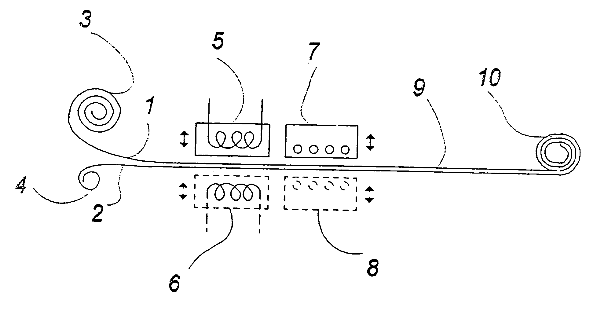
[0044] In FIG. 1 a schematic view of a preferred automated embodiment according to the invention is shown.

[0045] In this embodiment, the apparatus is fed by endless webs of PTFE foil 1 and PTFE coated glass fibre fabric 2 from a roll of PTFE foil 3 and a roll of PTFE coated glass fibre fabric 4. The finished composite 9 is wound up on a roll 10.

[0046] According to this embodiment the webs 1 and 2 move relative to the apparatus. The rollers 3, 4 and 10 are rotated by forwarding means (not shown in FIG. 1) in an intermittent movement between two cooperating heated pressure surfaces 5 and 6. These pressure surfaces 5, 6 are connected to hydraulic pressure- and movement means (not shown in FIG. 1) and adapted to perform a relative movement to and from the two webs 1 and 2.

[0047] The above stepwise movement in the longitudinal direction essentially corresponds to the pressure surfaces 5, 6.

[0048] When the stepwise movement has fed two new partial lengths of foil 1 and glass fabric 2 ...


PUM

PropertyMeasurementUnit
pressureaaaaaaaaaa
shrinkageaaaaaaaaaa
temperatureaaaaaaaaaa

Abstract

The invention relates to a method of manufacture of a composite product including at least one layer of reinforced woven material and at least one layer of PTFE foil or ePTFE foil, where the foil or foils are laminated together with the layer or layers of woven material under the use of heating and pressurizing, where the composite material subsequently is cooled to a fully or partly fixed state. According to a preferred embodiment the composite is fixated by means of one or two cooperating pressure surfaces under a relative high pressure. By the invention a form stable composite material having a considerable enhanced E-modulus is achieved.

Description

[0001] This application is a Continuation of application Ser. No. 09 / 485,097, filed Mar. 8, 2000, which is a National Stage Application of PCT / DK98 / 00342, filed Aug. 8, 1998, which application are incorporated herein by reference.FIELD OF THE INVENTION [0002] The invention relates to a method of manufacture of a composite material having at least one layer of reinforced woven material and at least one layer of PTFE foil or ePTFE foil, a composite product having at least one layer of reinforced woven material and at least one layer of PTFE foil or ePTFE foil, and an apparatus for manufacture of a composite material having at least one layer of reinforcing woven material and at least one layer of PTFE foil or ePTFE foil. BACKGROUND OF THE INVENTION [0003] Composite products comprising a reinforcing woven material and a PTFE foil are used for many different industrial purposes. Within the chemical industry, this kind of material is, for example, used for vessels, compensators, containe...

Claims


Application Information

Patent Timeline
Patent Type & Authority Applications(United States)
IPC IPC(8): B32B27/12
CPCB29C66/0342B29C66/71B32B2327/18B32B2305/18B32B38/1875B29C66/7212B29C66/81465B29C66/8322B29C66/83221B29C66/83413B29K2027/18B29K2105/06B29K2309/08B32B27/12B32B37/08B29C66/72141B29C66/45B29C65/18B29C65/44B29C65/02B29C66/8242B29C66/1122Y10T442/3878B32B2307/734B32B27/322B32B5/024B32B2262/101B32B2309/025
Inventor MATHIESEN, BENNY MARTIN
Owner KE BURGMANN
Why Eureka
Try Eureka