
Method for regenerating an exhaust aftertreatment system

a technology of exhaust aftertreatment and regenerating system, which is applied in the direction of distance measurement, electrical control, instruments, etc., can solve the problems of increasing the exhaust gas emissions during the regeneration, affecting the system, and destroying the regeneration, so as to achieve low installation expenditure

Active Publication Date: 2005-08-04
ROBERT BOSCH GMBH
View PDF15 Cites 74 Cited by
  • Summary
  • Abstract
  • Description
  • Claims
  • Application Information

AI Technical Summary

Benefits of technology

[0009] The utilization of information relating to the travel distance for controlling the regeneration cycles makes it possible in a foresighted strategy to avoid, for example, the necessity of ending a regeneration operation of a particulate filter extending for several minutes as a consequence of unfavorable engine operating parameters or the possibility of damage to the aftertreatment system. The regeneration, which as a rule is associated with worse exhaust gas values than in normal operation, may also be adapted to external requirements, e.g., prevented in a tunnel.
[0010] An advantageous utilization of information, accompanied by low installation expenditure, is achieved in that the information is supplied by a global positioning system, a traffic telematics system, a travel distance computer and / or a navigation system.

Problems solved by technology

Under unfavorable operating conditions, increased exhaust gas emissions may occur during the regeneration.
For example, during the thermal regeneration of diesel particulate filters, a transition into overrun condition or idling after the start of regeneration is detrimental to the completeness of the soot burn-off or will even damage the system if the filter is too heavily loaded.
When a transition is made into overrun operation or idling, there is the danger that if the filter is heavily loaded, the exhaust gas mass flow diminishes, while the partial pressure of oxygen simultaneously increases.
This may result in a temperature increase in the diesel particulate filter, which may cause its destruction.
Such temperatures are not reliably reached in vehicle operation, making additional measures necessary for the regeneration.
However, it is not possible to always ensure this in modern diesel vehicles, making it possible for excess particulate matter to accumulate in the filter, resulting in high backpressures and a reduction of performance in the internal combustion engines.
However, all such measures require additional energy (heat) which is ultimately generated from the fuel (e.g., electrical energy from the battery to generate heat in a heating element, a fuel burner, postinjection of fuel into the engine combustion chamber).
The exhaust emission control system thus increases the fuel consumption of the vehicle.

Method used


Image

  • Method for regenerating an exhaust aftertreatment system
  • Method for regenerating an exhaust aftertreatment system

Examples


Embodiment Construction

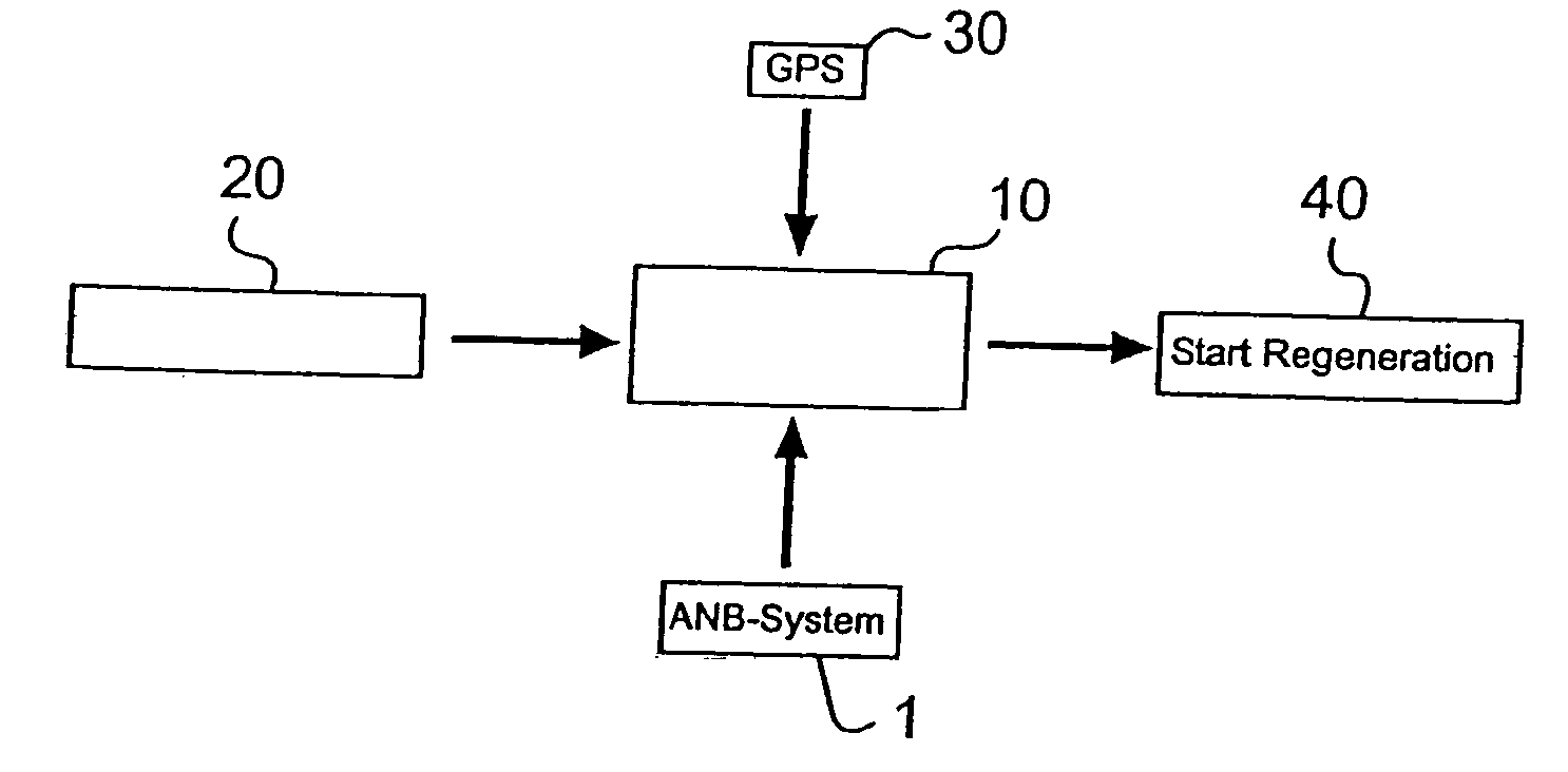
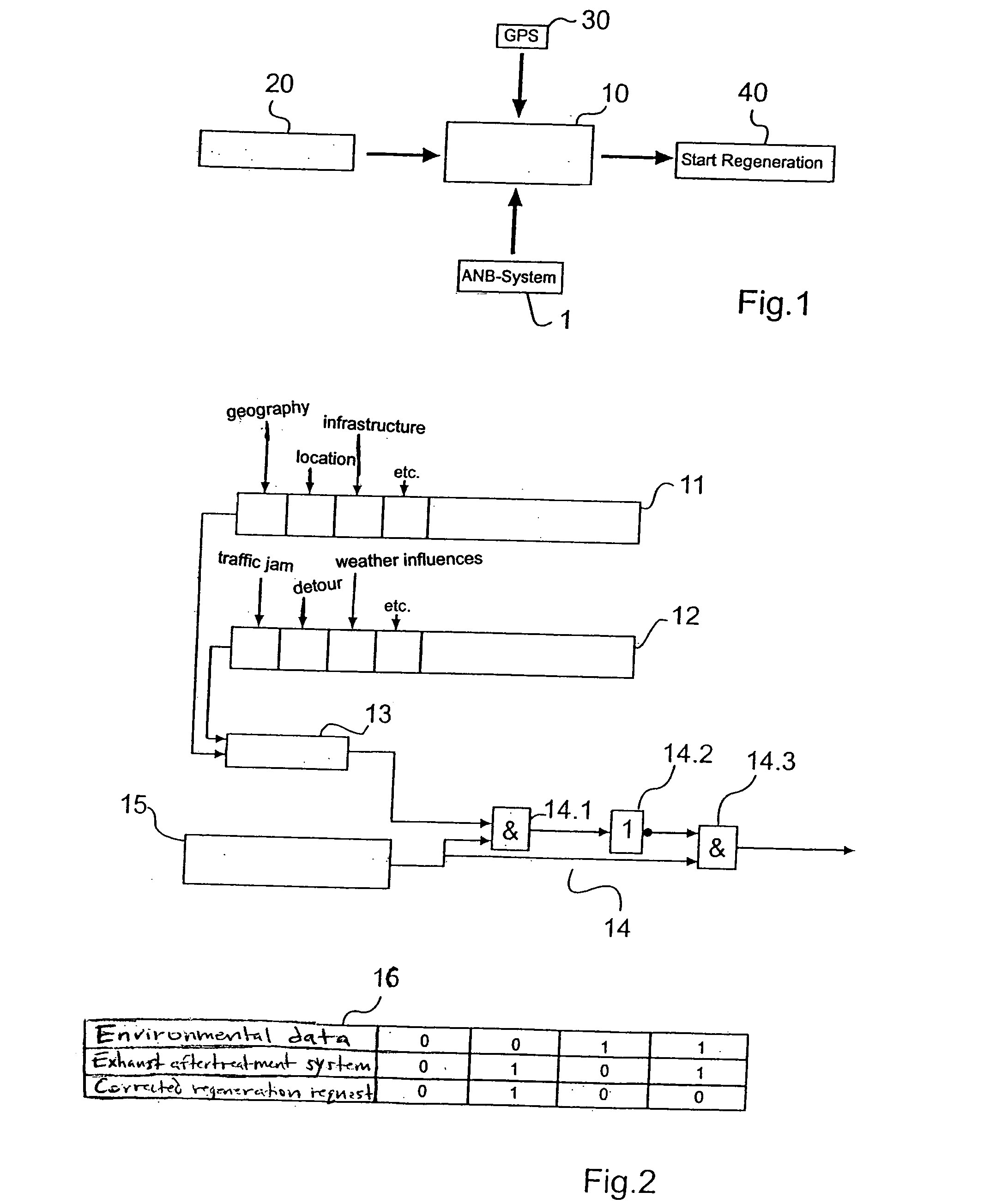
[0019] According to FIG. 1, for the regeneration, in addition to the signals, i.e., data of an exhaust aftertreatment system 1, information from a global positioning system (GPS) 30 and / or a traffic telematics system 20 relating to the travel distance by the vehicle is supplied to a control device 10 having a state machine in order to start a regeneration of the aftertreatment system via a suitable device 40. The exhaust aftertreatment system to be regenerated is associated with an internal combustion engine situated in a vehicle.

[0020] Using the information from global positioning system 30 or traffic telematics system 20 or a similar system including a travel distance computer and / or navigation system, supplied to control device 10, it is possible to create a foresighted regeneration strategy as a function of the travel distance, which is determined in control device 10 in conjunction with the data of exhaust aftertreatment system 1. The regeneration strategy is directed to avoid...


PUM


Abstract

A method for regenerating an exhaust aftertreatment system, in particular a particulate filter of an internal combustion engine, situated in a vehicle, having regeneration cycles controlled by a control device. An optimized regeneration of the exhaust aftertreatment system is achieved by supplying information relating to the travel route to the control device and controlling the regeneration cycles, taking the information into consideration.

Description

FIELD OF THE INVENTION [0001] The present invention relates to a method for regenerating an exhaust aftertreatment system, in particular a particulate filter of an internal combustion engine, situated in a vehicle, having regeneration cycles controlled by a control device. BACKGROUND INFORMATION [0002] A method for regenerating an exhaust aftertreatment system is carried out as a function of defined engine operating states based on parameters which are relevant in this respect. The regeneration cycles include the actual regeneration operation and a specific period between the individual regeneration operations. The regeneration in part requires changes in the engine operating state in the particular instantaneous engine operating point characterized by load torque and rotational speed. These may be, for example, measures to increase the exhaust gas temperature during the thermal diesel particulate filter regeneration. Measures to increase the exhaust gas temperature are, for example...

Claims


Application Information

Patent Timeline
Patent Type & Authority Applications(United States)
IPC IPC(8): F01N3/02F01N3/023F01N3/08F01N9/00F02D41/02F02D41/40
CPCF01N3/023F01N3/0871F01N9/002Y02T10/47F02D41/405F02D2200/0802F02D2200/701F02D41/029Y02T10/40
Inventor PFAEFFLE, ANDREASWIRTH, RALFWUEST, MARCELLUEDERS, HARTMUTHAUBER, THOMAS
Owner ROBERT BOSCH GMBH
Learn More