Injection controller for internal combustion engine

a technology for injection controllers and internal combustion engines, which is applied in the direction of electric control, machines/engines, mechanical equipment, etc., can solve the problems of obstructing the injection of fuel, increasing the temperature of the nozzle hole, and causing unsatisfactory combustion

Active Publication Date: 2005-08-04
TOYOTA JIDOSHA KK
View PDF5 Cites 130 Cited by
  • Summary
  • Abstract
  • Description
  • Claims
  • Application Information

AI Technical Summary

Benefits of technology

[0007] It is an object of the present invention to provide an injection controller for internal combustion engines which ideally suppresses the accumulation of deposits on the nozzle hole of the direct injection valve.

Problems solved by technology

However, when the direct injection valve is not injecting fuel, the nozzle hole is not cooled by vaporized fuel and the temperature of the nozzle hole increases such that deposits accumulate on the nozzle hole.
Such deposits obstruct the injection of fuel from the nozzle hole of the direct injection valve.
There is concern in this case that misfire and unsatisfactory combustion may occur.
Therefore, an adequate cooling effect is not obtained, and the accumulation of deposits is not sufficiently prevented.
In this case, there is concern that misfire and unsatisfactory combustion may occur.

Method used


Image

  • Injection controller for internal combustion engine
  • Injection controller for internal combustion engine
  • Injection controller for internal combustion engine

Examples


first embodiment

[0017] An injection controller 50 for an internal combustion engine 10 according to a first embodiment of the present invention will now be described with reference to FIGS. 1 and 2.

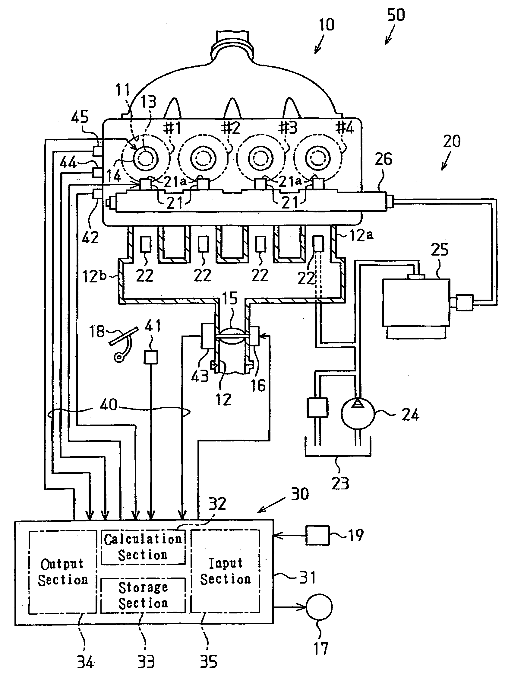
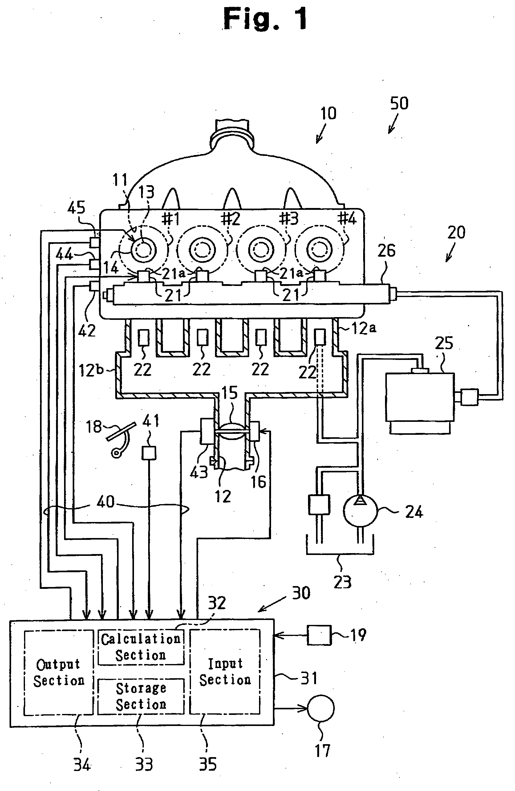
[0018]FIG. 1 is a schematic diagram showing the injection controller 50 of the first embodiment.

[0019] The injection controller 50 is provided with a fuel supply system 20 for supplying fuel to the internal combustion engine 10, a control system 30 for controlling fuel injection with the fuel supply system 20, and a detection system 40 having various types of sensors for providing the control system 30 with detection signals (some of the control data).

[0020] In the first embodiment, the internal combustion engine 10 has four cylinders #1 through #4. Each of the cylinders #1 through #4 includes a combustion chamber 11 connected to an intake passage 12. Specifically, the intake passage 12 includes four intake ports 12a, each of which is connected to a corresponding one of the combustion chambers 11, and...

second embodiment

[0055] A fuel injection controller 50 of an internal combustion engine 10 according to a second embodiment of the present invention will now be described with reference to FIGS. 3 and 4 focusing on parts differing from the first embodiment.

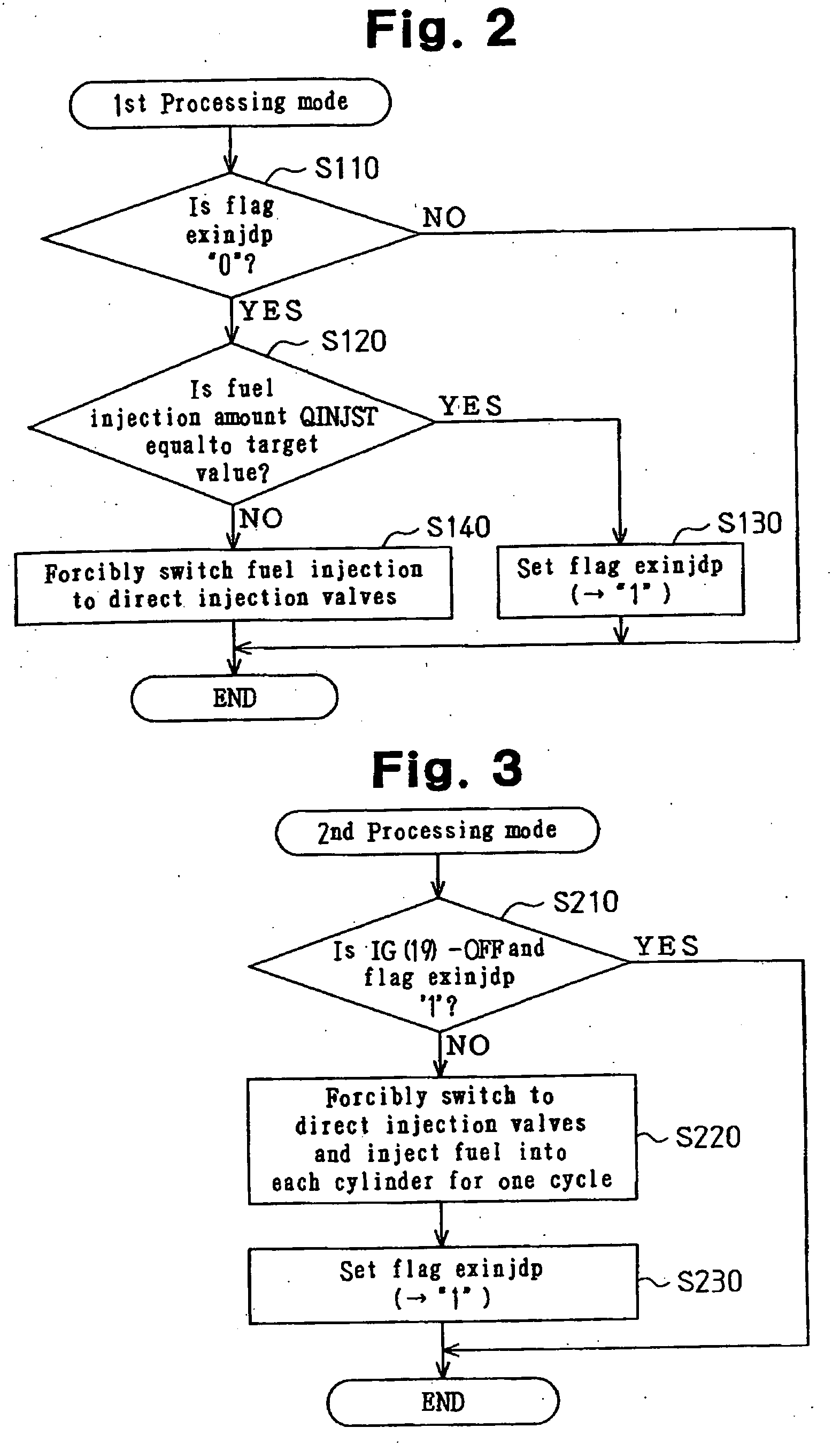
[0056] In the second embodiment, the ECU 31 executes a control routine corresponding to a second processing mode in addition to the control routine corresponding to the first processing mode of the first embodiment in order to switch the fuel injection mode. These control routines are stored in the storage section 33 of the ECU 31.

[0057]FIG. 3 is a flowchart showing the control routine of the second processing mode. The second processing mode is designed for deposit prevention by forcibly switching the injection valve from the port injection valve 22 to the direct injection valve 21 until the engine stops after the ignition switch 19 is turned OFF based on the mode control flag exinjdp of the first processing mode. This control routine is execut...

third embodiment

[0072] A fuel injection controller 50 of an internal combustion engine 10 according to a third embodiment of the present invention will now be described with reference to FIG. 5 focusing on parts differing from the first and second embodiments.

[0073] In the third embodiment, the ECU 31 executes a control routine corresponding to a third processing mode to switch the fuel injection mode. This control routine is stored in the storage section 33 of the ECU 31.

[0074]FIG. 5 is a flowchart showing the control routine of the third processing mode. In the third processing mode, the ECU 31 estimates the amount of deposits accumulated on the nozzle hole 21a of each direct injection valve 21 when the engine is operating with fuel continuously injected from the port injection valves 22. The ECU 31 performs deposit prevention by forcibly switching the injection valves from the port injection valves 22 to the direct injection valves 21 for a predetermined interval based on this estimation. This...


PUM


Abstract

An injection controller for an internal combustion engine that suppresses the accumulation of deposits on a nozzle hole of a direct injection valve. The injection controller includes the direct injection valve, which injects fuel into a cylinder, and an intake passage injection valve, which injects fuel into an intake passage. An ECU, which is connected to the direct injection and intake passage injection valves, executes a first fuel injection mode for injecting fuel with the direct injection valve and a second fuel injection mode for injecting fuel with the intake passage injection valve. The ECU switches fuel injection modes from the second fuel injection mode to the first fuel injection mode for a predetermined period when fuel is to be injected in the second fuel injection mode.

Description

BACKGROUND OF THE INVENTION [0001] The present invention relates to an injection controller for an internal combustion engine, and more specifically, relates to an injection controller for an internal combustion engine provided with a direct fuel injection valve, which injects fuel directly into the cylinder, and an intake passage fuel injection valve, which injects fuel into an intake passage. [0002] Conventionally, certain internal combustion engines are provided with a direct injection valve (in-cylinder injection valve) for injecting fuel directly into the cylinder in addition to a port injection valve for injecting fuel into an intake port of an intake passage (for example, refer to Japanese Laid-Open Patent Publication No. 2002-364409). In such an internal combustion engine, the fuel injection is flexibly switchable in accordance with the engine operation conditions such that fuel injection is performed by only the port injection valve, fuel injection is performed by only the ...

Claims


Application Information

Patent Timeline
Patent Type & Authority Applications(United States)
IPC IPC(8): F02M51/00F02D41/04F02D41/22F02D41/30F02D41/32F02D41/34F02D41/36F02D41/40F02D45/00F02M51/06
CPCF02D41/3029F02D41/3094Y02T10/44F02D2041/389F02D41/40F02D41/042Y02T10/40
Inventor SADAKANE, SHINJITSUCHIYA, TOMIHISAIKOMA, TAKUYA
Owner TOYOTA JIDOSHA KK
Why Eureka
Try Eureka