Three-conductor cable

a three-conductor cable and conductor technology, applied in the direction of power cables, conductors, power cables including electrical control, etc., can solve the problems of reducing the voltage drop of inductive devices, affecting the performance of the inductive device, and requiring high-quality insulation materials to meet the requirements of high-quality insulation materials, so as to achieve a positive effect on the voltage drop

Inactive Publication Date: 2005-08-04
LEONI STUDER
View PDF2 Cites 13 Cited by
  • Summary
  • Abstract
  • Description
  • Claims
  • Application Information

AI Technical Summary

Benefits of technology

[0011] The three-conductor cable thus contains one concentric, external neutral and / or return line per phase conductor, which, however, in completely symmetrical operation practically never has to be used. Only a small inductance results from the geometrical structure, and this has a positive effect on the voltage drop.

Problems solved by technology

This asymmetry results in a detrimental inductive voltage drop, which takes on great significance especially in cables which are used at the higher frequency range.
Asymmetrical electrical fields also arise due to the geometry of this known four-conductor cable, which can propagate interference to the immediate environment.
This is a disadvantage when there is an asymmetrical load, as often occurs with wide-body aircraft.
Although in operational status the construction has relatively low inductance, it is expensive and usually fairly inflexible.
It also requires insulation of two parallel three-phase systems, which means additional expense for high-quality insulation material.
This second type of high-frequency power transmission cable thus demonstrates the disadvantage of a complicated and relatively expensive manufacture.

Method used


Image

  • Three-conductor cable
  • Three-conductor cable

Examples


Embodiment Construction

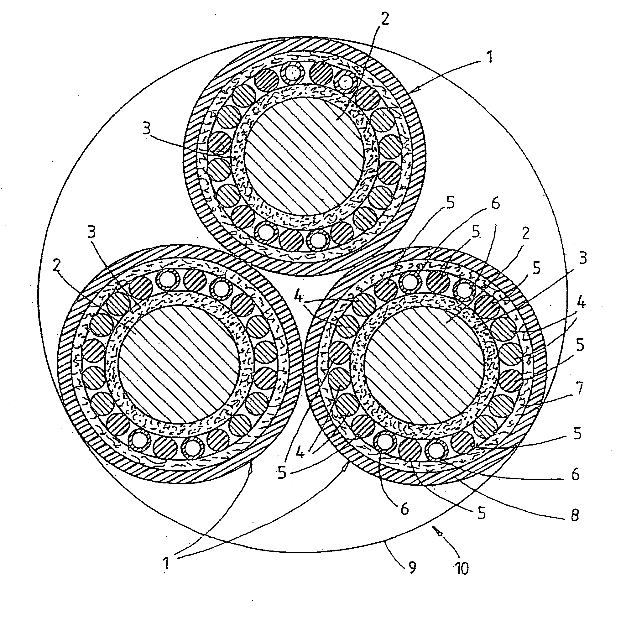
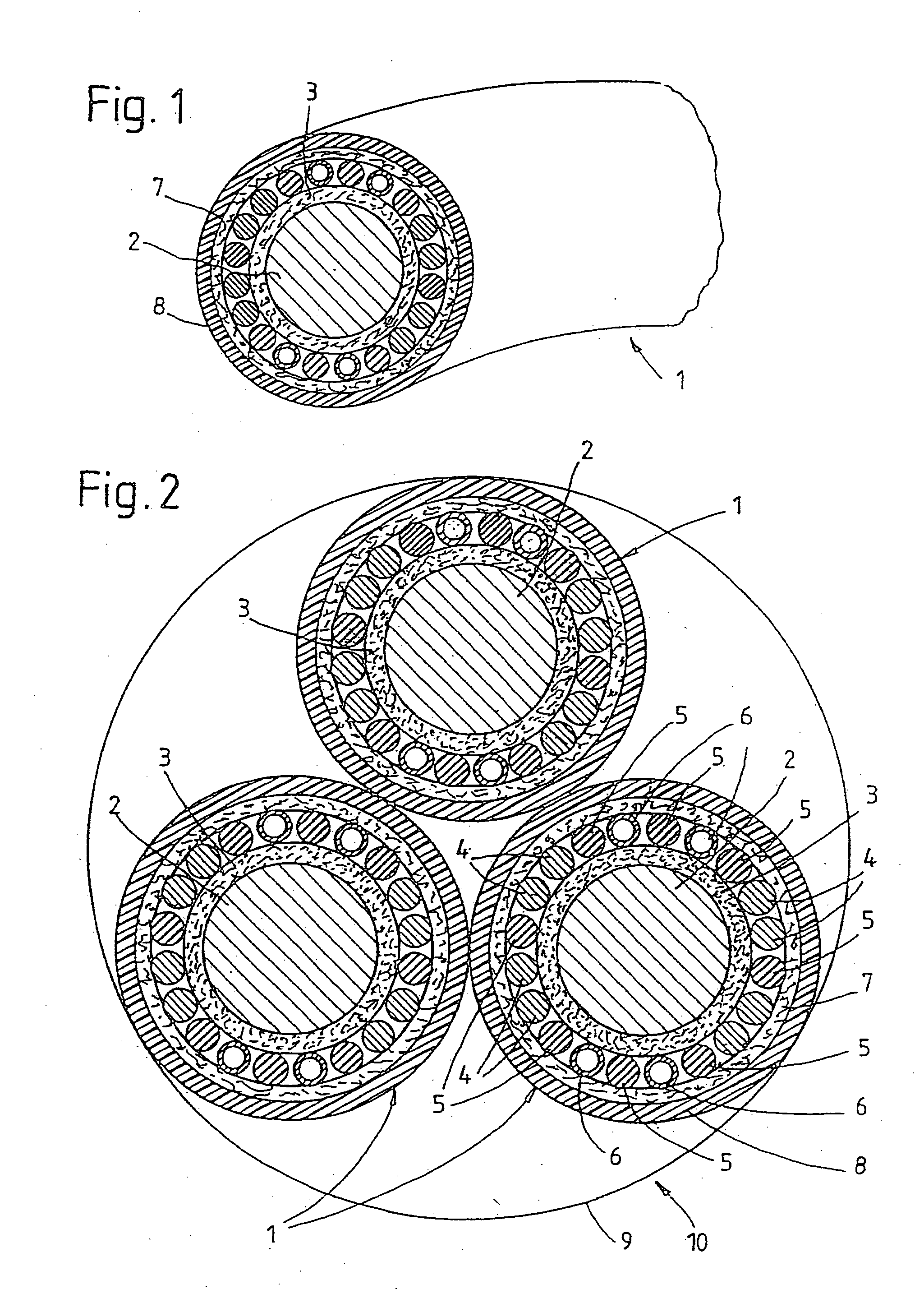
[0016] The electrical cable shown in FIG. 1 separately and in FIG. 2 intertwined with identical cables and referred to as a whole by the number 1 has a conductor conductor, namely an inner conductor 2 with several intertwined wires.

[0017] The inner conductor 2 is encased by a protective sheath 3, preferably made of plastic, hereinafter also referred to as insulation.

[0018] Embedded in the concentrically-running neutral and / or return line, formed for example by eight component conductors 4, are dummy conductors 5 and control conductors 6 which for their part are coupled for control, monitoring, measurement and command purposes.

[0019] Over the component conductors 4 of the neutral and / or return line, the dummy conductors 5 and the control conductors 6 is applied a fleece band 7 and over that a protective sheath 8 preferably made from plastic.

[0020] The following details which relate to the diameter of the various layers are given by way of example and relate to an electrical cable...


PUM

PropertyMeasurementUnit
frequencyaaaaaaaaaa
frequencyaaaaaaaaaa
frequencyaaaaaaaaaa

Abstract

The invention relates to a three-conductor cable (10) consisting of three stranded electric cables (1), each comprising a core that has a current conductor (2) and a neutral and/or return conductor. Each individual cable (1) is essentially characterised in that the neutral and/or return conductor is configured from a number of individual conductors (4), distributed concentrically around the current conductor (2), that an insulating sheath (3) is provided between the current conductor (2) and the distributed individual conductors (4) of the neutral and/or return conductor and that a protective jacket covers the neutral and/or return conductor.

Description

TECHNICAL DOMAIN [0001] The invention concerns a three-conductor cable for power transmission at a frequency of at least 50 Hz, preferably at least 100 Hz, for example 400 Hz. [0002] In the 400 Hz range, what are referred to as high-frequency power transmission cables are used. They are required for example on aircraft and suchlike, in order to connect them during stationary periods to a fixed network or a mobile power supply. Because the aircraft's on-board electronics are highly sensitive to current fluctuations, the cable must not generate any damaging asymmetrical voltage drops. [0003] Another domain of application is engine technology. Thus, for example, high-frequency power transmission cables can also be used to power motors for spindle drives (induction / synchronous motors) or brushless DC motors. STATE OF THE ART [0004] Known high-frequency cables for frequencies of 400 Hz and above consist of four intertwined component conductors, consisting of three phase conductors and a ...

Claims


Application Information

Patent Timeline
Patent Type & Authority Applications(United States)
IPC IPC(8): H01B9/00H01B9/04
CPCH01B9/04H01B9/003
Inventor STUDER, CHRISTOPH
Owner LEONI STUDER
Why Eureka
Try Eureka