Imaging methods for fluorescence and reflectance imaging and spectroscopy and for contemporaneous measurements of electromagnetic radiation with multiple measuring devices

a technology of electromagnetic radiation and imaging device, which is applied in the direction of optical radiation measurement, fluorescence/phosphorescence, instruments, etc., can solve the problems of increasing the cost and weight of imaging device, and achieve the effect of enhancing the ability to point the devi

Inactive Publication Date: 2005-08-04
VERISANTE TECH
View PDF33 Cites 48 Cited by
  • Summary
  • Abstract
  • Description
  • Claims
  • Application Information

AI Technical Summary

Benefits of technology

[0021] The present invention provides these and other needs by providing optical systems that provide for simultaneous images and spectra from an object, such as a tissue sample, an industrial object such as a computer chip, or any other object that can be viewed with an optical system such as a microscope, endoscope, telescope or camera. In some embodiments, the present invention further provides systems that provide multiple images corresponding to various desired wavelength ranges within an original image of the object, as well as, if desired, directional pointer(s) that can provide both an identification of the precise location from which a spectrum is being obtained, as well as enhancing the ability to point the device.
[0022] In one aspect, the invention provides a method and apparatus for facilitating contemporaneous measurements of electromagnetic radiation with multiple measuring devices. The method involves causing first and second adjacent groups of rays of an electromagnetic radiation beam to be directed for receipt by first and second measuring devices respectively. The apparatus includes a beam-directing device locatable to cause the first and second adjacent groups of rays to be directed in this manner.
[0023] Thus, a first group of rays may be directed for receipt by a spectrometer, for example, while the second, adjacent group of rays may be directed to an imaging device such as a camera. In such a case, none of the second group of rays would be directed to the spectrometer, and accordingly, the second group of rays may arrive essentially undiminished at the camera, resulting in a brighter image than would be possible using a semi-transparent beam splitter, for example. In many applications, this may eliminate the need for expensive signal amplification devices, such as image intensifiers, which introduce noise, and which also increase the cost and weight of the imaging device. In addition, the image produced by such an imaging device in response to the second group of rays will have a black spot corresponding to the original paths of the first group of rays which have been directed to the other measuring device, e.g. the spectrometer. Thus, by observing the location of the black spot in the image produced in response to the second group of rays, an observer such as a surgeon or physician for example, will immediately know the precise point that is being sampled by the spectrometer and will therefore know whether the spectrometer is measuring a point in the desired area of interest, such as a suspicious looking area in the image produced in response to the second group of rays. In addition, this method may be effectively used to allow for both the first and second measuring devices, such as a camera and a spectrometer for example, to simultaneously produce measurements from a single electromagnetic radiation beam, without the need to produce a second separate beam, using a semitransparent beam splitter or an optical fiber passing through the biopsy channel of an endoscope, for example. Also, more accurate spectra may be obtained without a fiber probe touching the tissue.

Problems solved by technology

In many applications, this may eliminate the need for expensive signal amplification devices, such as image intensifiers, which introduce noise, and which also increase the cost and weight of the imaging device.

Method used


Image

  • Imaging methods for fluorescence and reflectance imaging and spectroscopy and for contemporaneous measurements of electromagnetic radiation with multiple measuring devices
  • Imaging methods for fluorescence and reflectance imaging and spectroscopy and for contemporaneous measurements of electromagnetic radiation with multiple measuring devices
  • Imaging methods for fluorescence and reflectance imaging and spectroscopy and for contemporaneous measurements of electromagnetic radiation with multiple measuring devices

Examples


first embodiment

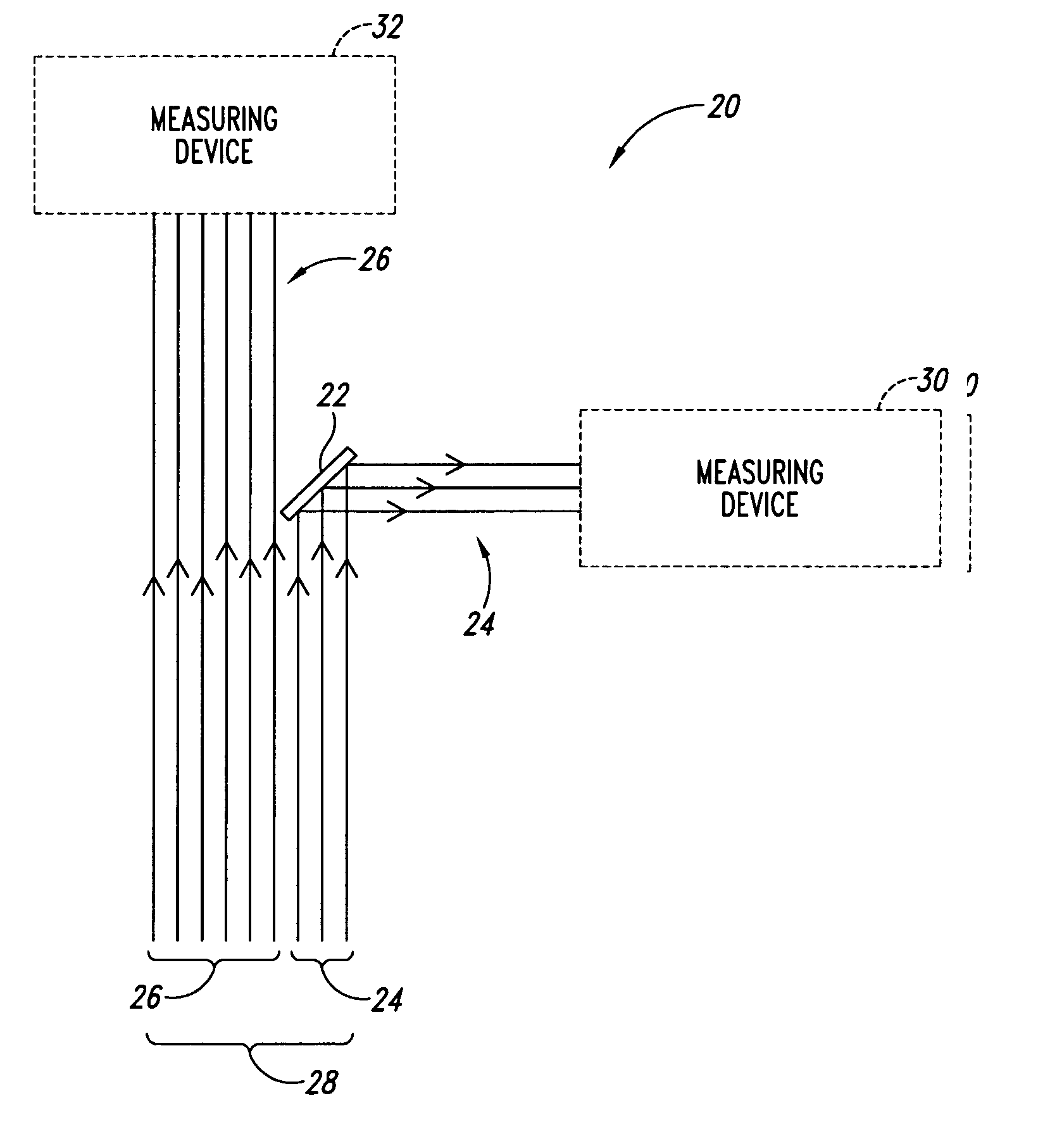
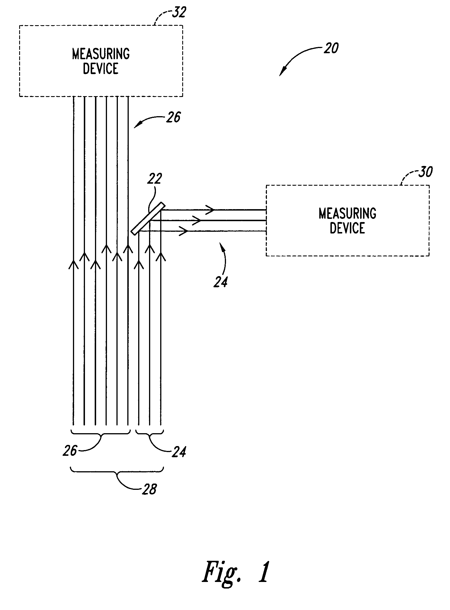
[0127] Referring to FIG. 1, an apparatus for facilitating contemporaneous measurements of electromagnetic radiation with multiple measuring devices, according to the invention is shown generally at 20. The apparatus 20 includes a beam-directing device 22 locatable to cause first and second adjacent groups 24 and 26 of rays of an electromagnetic radiation beam 28 to be directed for receipt by first and second measuring devices 30 and 32 respectively.

System

second embodiment

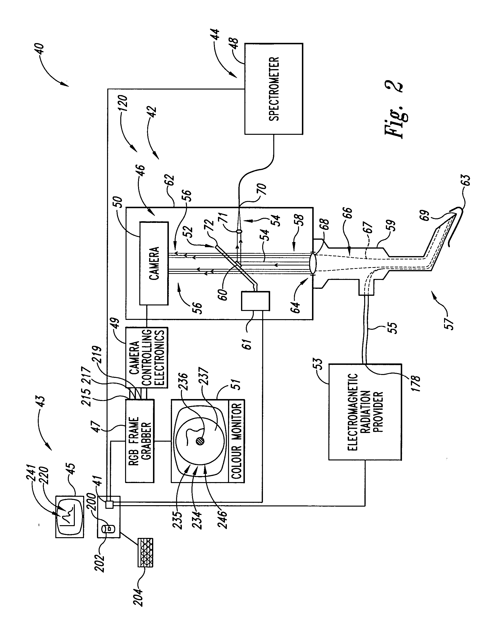
[0128] Referring to FIG. 2, an electromagnetic radiation measuring system is shown generally at 40. The system 40 includes an apparatus 42 for facilitating contemporaneous measurements of electromagnetic radiation with multiple measuring devices, according to the invention. The system 40 includes first and second measuring devices 44 and 46, which in this embodiment include a spectrometer 48 and an imaging device, which in this embodiment is a charge-coupled device (CCD) camera 50, respectively. The apparatus 42 includes a beam-directing device 52 locatable to cause first and second adjacent groups 54 and 56 of rays of an electromagnetic radiation beam 58 to be directed for receipt by the first and second measuring devices 44 and 46 respectively.

[0129] The system 40 further includes a processor circuit 41, which in this embodiment is housed within or outside a general-purpose computer 43 which includes a monitor 45. The processor circuit 41 is in communication with the spectrometer ...


PUM

PropertyMeasurementUnit
green wavelengthsaaaaaaaaaa
IR wavelengthsaaaaaaaaaa

Abstract

Optical systems that provide for simultaneous images and spectra from an object, such as a tissue sample, an industrial object such as a computer chip, or any other object that can be viewed with an optical system such as a microscope, endoscope, telescope or camera. In some embodiments, the systems provide multiple images corresponding to various desired wavelength ranges within an original image of the object, as well as, if desired, directional pointer(s) that can provide both an identification of the precise location from which a spectrum is being obtained, as well as enhancing the ability to point the device.

Description

CROSS-REFERENCE TO RELATED APPLICATIONS [0001] The present application claims priority from U.S. patent application Ser. No. 09 / 741,731, filed Dec. 19, 2000, which is presently pending.FIELD OF THE INVENTION [0002] The present invention relates to electromagnetic radiation measuring devices, and more particularly to methods and apparatus for facilitating contemporaneous measurements of electromagnetic radiation with multiple measuring devices, for producing illuminating radiation for fluorescence and reflectance imaging, for performing both fluorescence and reflectance imaging using the same detectors in an imaging device, for producing a high diagnostic sensitivity image while achieving high diagnostic specificity with spectroscopy, for detecting tissue oxygenation, and for producing a fluorescence image of tissue. BACKGROUND OF THE INVENTION [0003] Many applications involve taking more than one type of measurement of electromagnetic radiation. For example, some medical imaging app...

Claims


Application Information

Patent Timeline
Patent Type & Authority Applications(United States)
IPC IPC(8): A61B1/00A61B1/04G01J3/02G01J3/10G01J3/36G01N23/223G01N21/64
CPCG01J3/0289G01J3/10G01J3/36G01N23/223G01N2223/076G01J3/021G01J3/0218G01J3/0235G01J3/0243G01J3/02
Inventor ZENG, HAISHANLAM, STEPHENPALCIC, BRANKO MIHAEL
Owner VERISANTE TECH
Why Eureka
Try Eureka