
Multi-screen video playback system

a video playback and multi-screen technology, applied in the field of multi-screen video playback systems, can solve the problems of difficult cost reduction, complicated handling of such systems, and general cost of memory, and achieve the effect of convenient constituted

Active Publication Date: 2005-08-04
SEIKO EPSON CORP
View PDF6 Cites 187 Cited by
  • Summary
  • Abstract
  • Description
  • Claims
  • Application Information

AI Technical Summary

Benefits of technology

[0017] Then, exemplary embodiments of the present invention have been made to address and / or solve these and / or other problems. Further, exemplary embodiments provide a multi-screen video playback system, which is a simple system which does not need to acquire the absolute time, can perform a synchronized and long hours of video playback easily, and also enables various video processing, such as color processing and resolution conversion, through the network. Exemplary embodiments further provide a video playback method in the multi-screen video playback system; a timing server, a video distribution server V and a rendering unit used for a multi-screen video playback system; and a display device to constitute a multi-screen display.
[0159] According to such a display device, by preparing the network and the video distribution server according to the above (35), separately, the multi-screen video device can be constituted easily. In addition, if the timing server is provided separately from the video distribution server, the multi-screen video device can be easily constituted by preparing the timing server and the like along with the video distribution server.

Problems solved by technology

For this reason, there are problems that the system becomes on a large scale, the handling thereof also becomes complicated, and the cost reduction thereof is not easy.
The memory is generally expensive, and even for video data of several minutes, it will be expensive to develop all of them to the memory.
Further, when it comes to video data of a movie which lasts for several hours, it is not easy to develop all of them to the memory.
Moreover, also in the synchronized playback method disclosed in Japanese Laid Open Patent Publication No. 2003-235027, since it is necessary to communicate with the time server like the above-described in Japanese Laid Open Patent Publication No. 2002-369163, there are problems that the system becomes on a large scale, its handling becomes also complicated, and its cost reduction is not easy.

Method used


Image

  • Multi-screen video playback system
  • Multi-screen video playback system
  • Multi-screen video playback system

Examples


exemplary embodiment 1

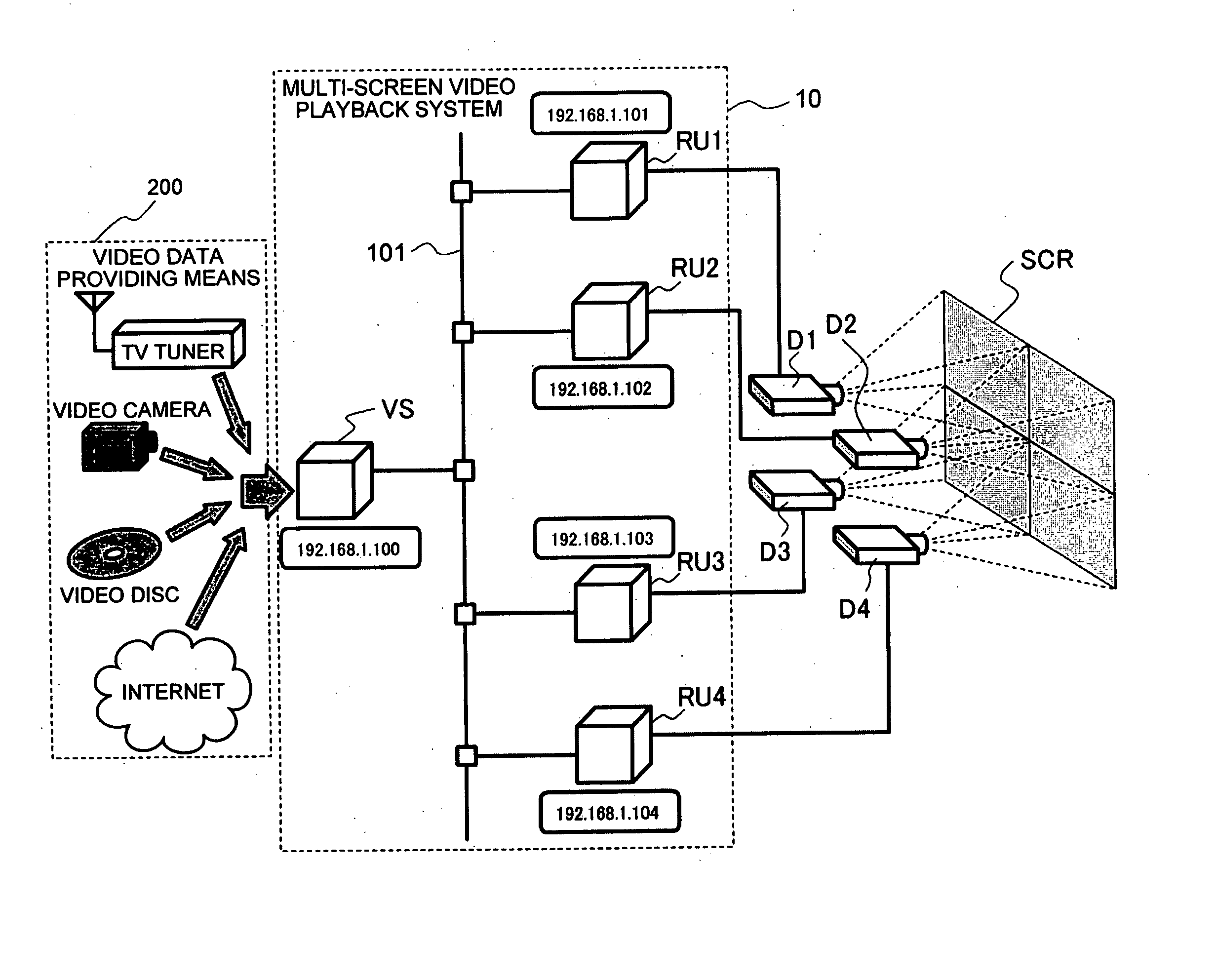
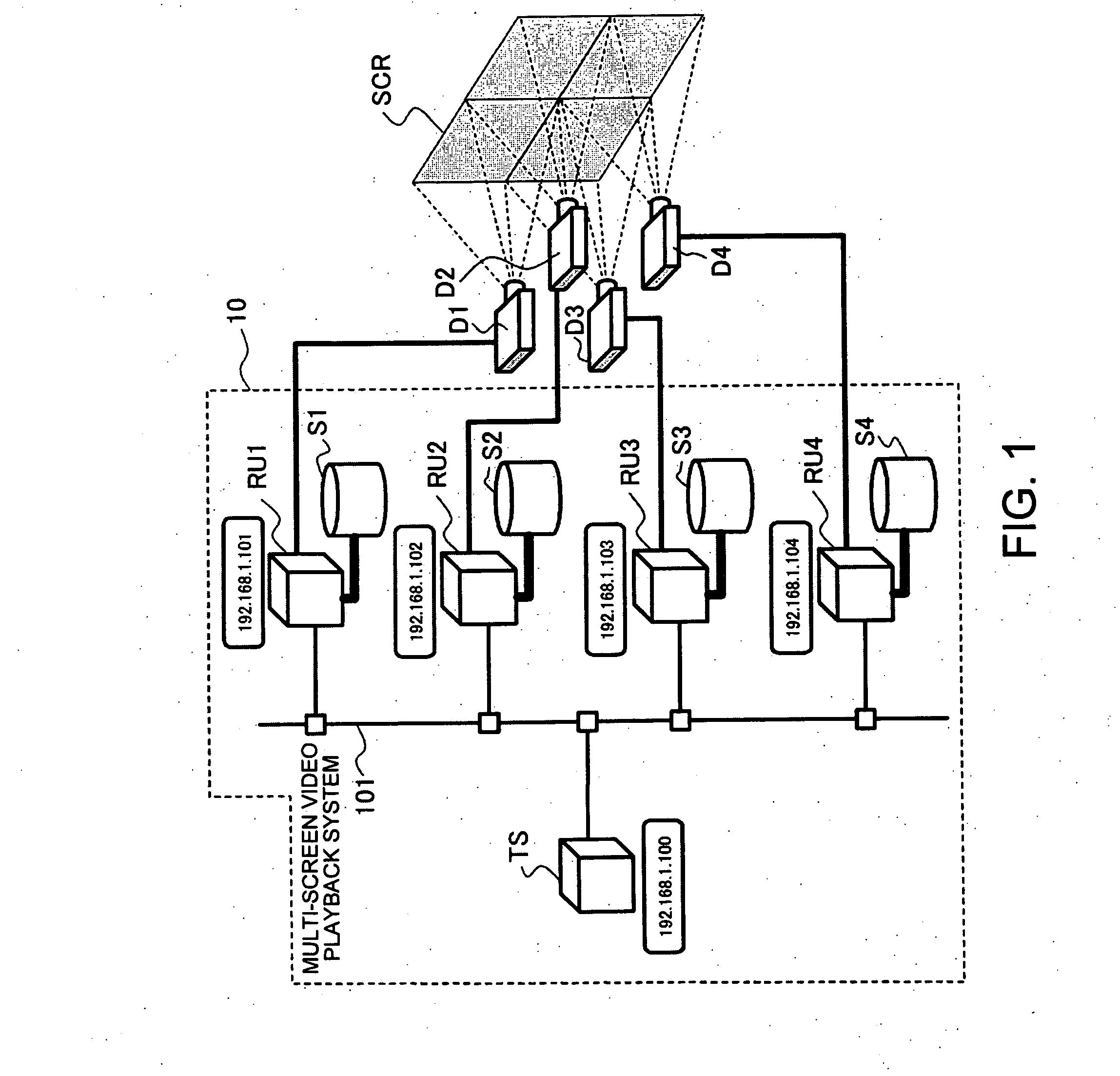
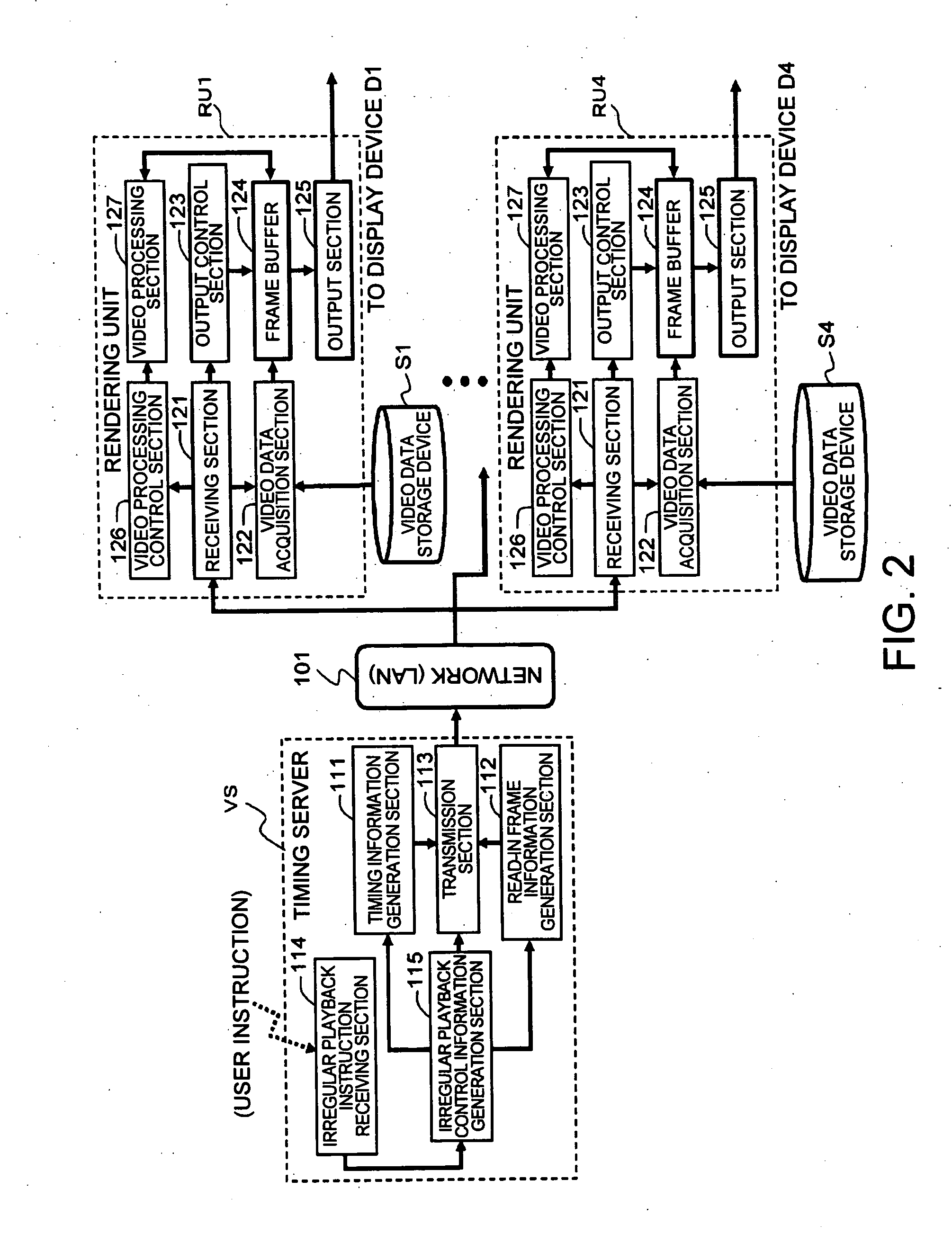
[0193]FIG. 1 and FIG. 2 are schematics showing a multi-screen video playback system according to an exemplary embodiment 1 of the present invention. The multi-screen video playback system 10 according to this exemplary embodiment 1 is, as shown in FIG. 1, a video playback device to output the synchronized video data to a plurality of display devices D1 through D4 (assuming the display device is a projector, in the exemplary embodiment of the present invention), which constitute the multi-screen display.

[0194] Moreover, the multi-screen display, to which the synchronized video data outputted by this multi-screen video playback system 10 is projected, consists of four sets of display devices D1 through D4 arranged in a matrix form of 2 lines by 2 rows (2×2), and reproduces one large screen video by combining an unit video (a partial video) which each of these display devices D1 through D4 projects onto a screen SCR.

[0195] In addition, the meaning of a “frame” used in the description...

exemplary embodiment 2

[0273] Although the above exemplary embodiment 1 is the case where the video data to be displayed is stored in the video data storage devices S1 through S4 provided in each of the rendering units RU1 through RU4 side, in this exemplary embodiment 2, a configuration in which the video data is distributed to each of the rendering units RU1 through RU4 through the network (LAN 101) will be described.

[0274]FIGS. 10 and 11 are schematics showing the configurations of the multi-screen video playback system according to the exemplary embodiment 2 of the present invention. Also, in the multi-screen video playback system 10 according to this exemplary embodiment 2, the multi-screen display is composed of, like the exemplary embodiment 1 four sets of display devices D1 through D4 arranged in a matrix form of two lines by 2 rows (2×2), and one large screen video is reproduced by combining a unit video (partial video) which each of these display devices D1 through D4 projects on the screen SCR...

exemplary embodiment 3

[0313] This exemplary embodiment 3 is an exemplary modification of the above exemplary embodiment 2, and differs from the exemplary embodiment 2, in a point that the video processing function to carry out the color processing, the resolution conversion, and the like, is given to the video distribution server side. In order to realize this, as shown in FIG. 17, in this exemplary embodiment 3, a video processing section 127 is provided at the video distribution server VS side.

[0314] Accordingly, in this exemplary embodiment 3, the configuration of the rendering units RU1-RU4 includes the receiving section 121, the video data acquisition section 122, the output control section 123, the frame buffer 124, and the output section 125.

[0315] In addition, the example of the whole system configuration of this exemplary embodiment 3 is the same as that of FIG. 10, and one example of the whole processing flow thereof is the same as that of FIG. 12, and the distribution timing of the video pac...


PUM

PropertyMeasurementUnit
timeaaaaaaaaaa
distribution timeaaaaaaaaaa
transmission timeaaaaaaaaaa

Abstract

Exemplary embodiments of the invention provide a multi-screen video playback system which enables synchronized video playback, and at the same time enables irregular playback such as color processing, contents change. According to exemplary embodiments, a multi-screen video playback system includes a plurality of rendering units RU1 through RU4 which are connected to LAN as a network and output video data to a plurality of display devices D1 through D4; a function which is connected to LAN and distributes timing information to the rendering units RU1 through RU4 by simultaneous transmission; a timing server TS which generates the irregular playback control information to enable irregular playback, such as color correction and contents change to the video data, in a plurality of rendering units RU1 through RU4 which output video data to each corresponding display device of the plurality of display devices D1 through D4; and video data storage devices S1 through S4 to store video data to be reproduced.

Description

BACKGROUND [0001] Exemplary embodiments of the present invention relate to a multi-screen video playback system suitable as a video playback device in a large multi-screen display, and the like, to a video playback method in a multi-screen video playback system, to a timing server, a video distribution server V and a rendering unit used in a multi-screen video playback system, and to a display device to constitute a multi-screen display. [0002]FIG. 30 is a schematic showing a multi-screen display. This multi-screen display D is a display device which constitutes one large screen by combining a plurality of display devices D1 through D4, such as a monitor and a projector, as shown in FIG. 30. The multi-screen video playback system is a video playback device to output a video signal which is inputted to each of the display devices D1 through D4, respectively, in such a multi-screen display D. [0003] In this multi-screen video playback system, as disclosed in the related art, a large s...

Claims


Application Information

Patent Timeline
Patent Type & Authority Applications(United States)
IPC IPC(8): G09G5/00H04N5/93G09G5/12G11B20/10H04N5/073H04N5/74H04N5/76H04N7/087H04N7/173H04N21/21H04N21/235H04N21/242
CPCH04N5/0736H04N5/76H04N9/3147H04N21/43615H04N21/4122H04N21/4307H04N21/4347H04N21/2365H04N21/43076
Inventor YAMADA, NORIHIKOHASEGAWA, HIROSHI
Owner SEIKO EPSON CORP
Learn More