Optical imaging apparatus

a technology of optical imaging and optical tubes, applied in the field of optical imaging apparatus, can solve the problems of inability to perform scrubbing and sterilization necessary for use in the body cavity, no probe detachment means, and organism damage, and achieve the effect of stable connection

Inactive Publication Date: 2005-08-04
OLYMPUS OPTICAL CO LTD
View PDF0 Cites 79 Cited by
  • Summary
  • Abstract
  • Description
  • Claims
  • Application Information

AI Technical Summary

Benefits of technology

[0010] Accordingly, it is a first object of the present invention to provide an optical imaging apparatus, wherein a stable connection can be secured between the optical fiber of the optical scanning probe and the optical fiber of the observation apparatus, even in the event that shifting of the shafts, inclination in the angle, and slack in the shaft direction occur at the connector portion between the rotating shaft of the rotation transmitting means provided to the optical scanning probe and the rotating shaft of the rotation driving means provided to the observation apparatus.

Problems solved by technology

However, no probe detaching means is provided, so scrubbing and sterilization necessary for use in the body cavity cannot be performed.
Also, the optical element such as the prism at the tip end is exposed from the external sheath and rotates in that state, so there is the possibility that the organism may be damaged.
However, according to this art, rotational force is not transmitted smoothly unless the rotational shaft of the rotation transmitting means for rotating the rotating tube provided within the connector portion of the optical probe, and the rotational shaft of the rotation driving means provided in the observation apparatus are precisely matched, resulting in irregularities and instability in the rotating speed, but in practice, it is difficult to match the two rotational shafts in a precise manner.
Further, the rotation transmitting means at the base portion of the rotating tube and the optical fiber connecting member are formed integrally, so in the event that any inclination occurs between the two, or in the event that slack occurs in the bearing supporting the rotating shafts so as to move in the direction of the fiber, the connection of the optical fiber of the optical probe and the optical fiber of the observation apparatus becomes unstable, which has been a problem.
Particularly, in the case of the single mode fiber used for OCT, there is the need to abut the fiber cores at a precision in the order of several μm, so even slight shifting or a slight gap at the fiber ends results in massive loss of light, deterioration in the observation S / N ratio, and irregularities in the intensity of the observed image due to change in the connection state owing to rotation.

Method used


Image

  • Optical imaging apparatus
  • Optical imaging apparatus
  • Optical imaging apparatus

Examples


first embodiment

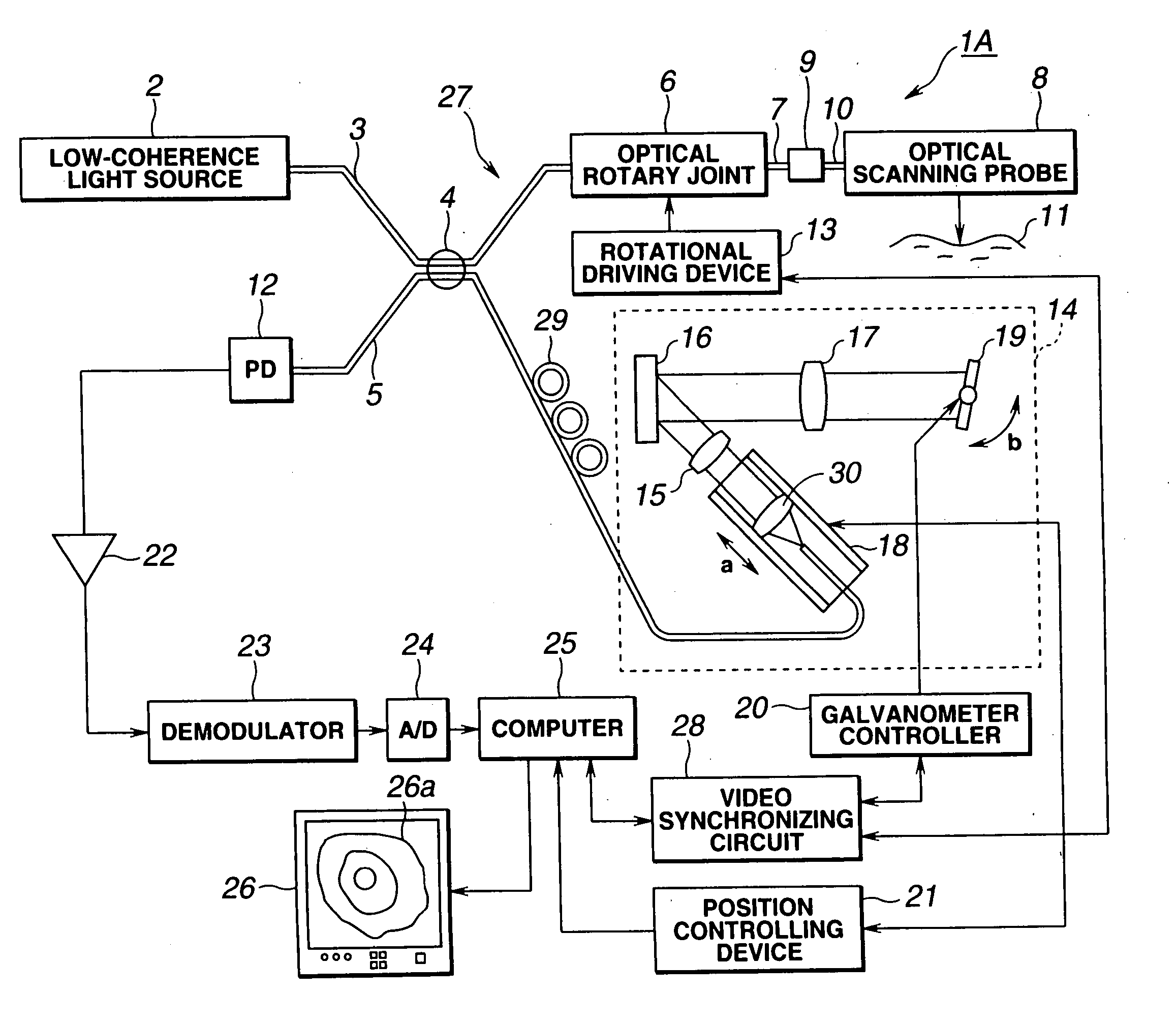
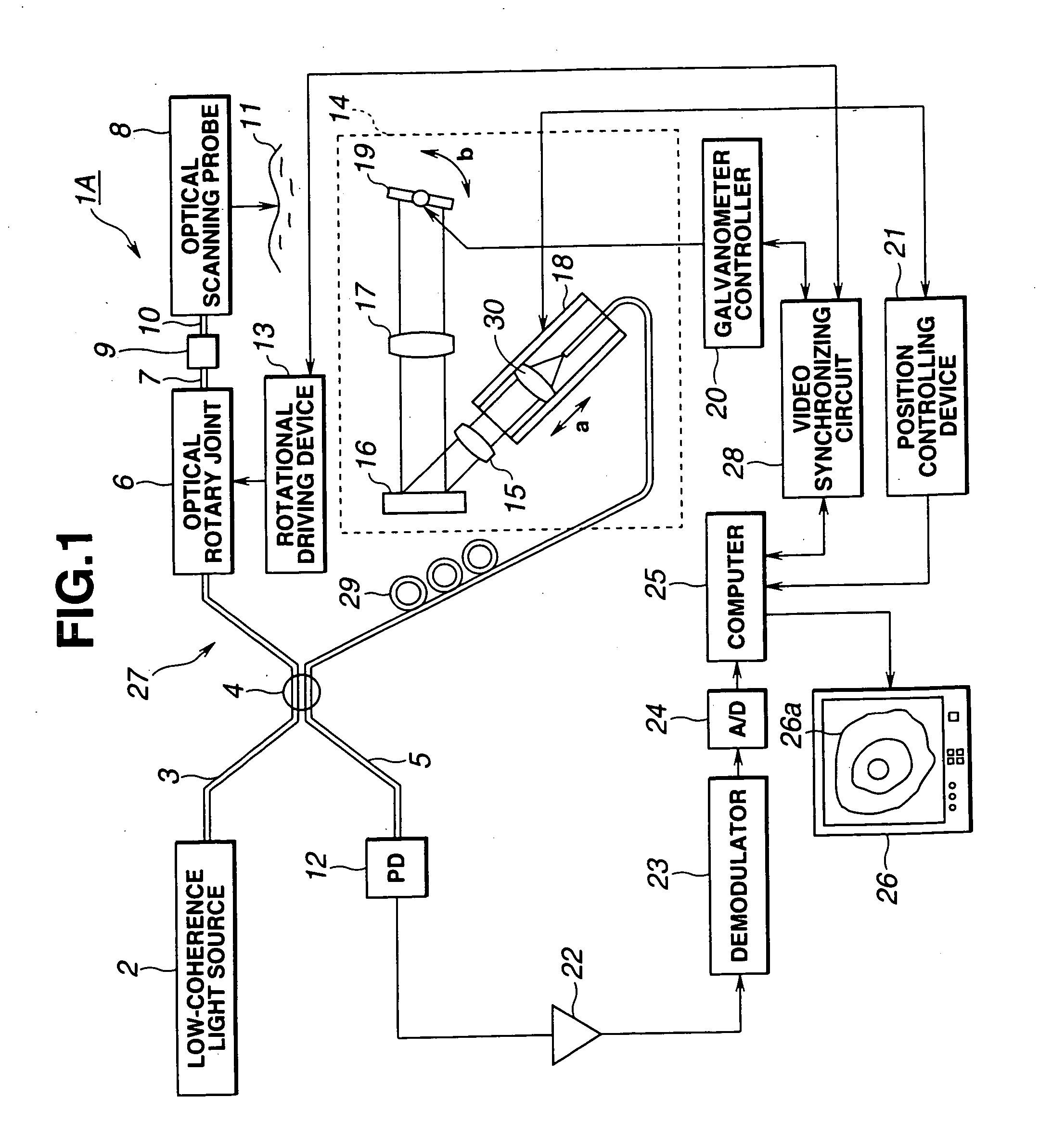
[0088] the present invention will now be described with reference to FIG. 1 through FIG. 7B.

[0089] An object of the present embodiment is to prevent shifting of the shafts, inclination in the angle, and slack in the shaft direction from occurring between the rotating shaft of the rotation transmitting means provided to the optical scanning probe and the rotating shaft of the rotation driving means provided to the observation apparatus, and to secure a stable connection between the optical fiber of the optical probe and the optical fiber of the observation apparatus.

[0090] Also, another object is to secure a good optical connection by allowing the detachable single mode fiber provided to the connection portion of the observation apparatus and optical probe to be replaced without re-polishing even in the event that the fiber end at the observation apparatus side to be optically connected to the fiber end portion of the optical scanning probe is soiled.

[0091] Further, another object ...

second embodiment

[0161] Next, a second embodiment according to the present invention will be described with reference to FIGS. 8A and 8B.

[0162] The objects of the present embodiment are the same as those of the first embodiment.

[0163] The difference with the arrangement shown in FIG. 5 will be described below, and other configurations are the same as those of the first embodiment. A shaft retainer 103 is provided instead of the shaft retainer 68.

[0164] The ferrule 71 is connected to a ferrule retainer 104, with the connector housing 105 and ferrule retainer 104 being slidable in the horizontal direction (the axial direction of the single mode fiber 10), and the ferrule retainer 104 is pressed to the right by the elastic force of the spring 106.

[0165] The base side of the connector housing has a tapered portion 105a provided thereto, coming into contact with the curved portion 108 of a sliding member 107 formed of a sliding plastic such as Derlin, provided to the shaft retainer 103.

[0166] Contact...

third embodiment

[0172]FIG. 9 shows the configuration of the connector connecting portion of the connector portion and rotation driving device according to the

[0173] The difference between the third embodiment shown in FIG. 9 and the first embodiment shown in FIG. 5 is that while with the first embodiment the optical adapter of the rotation driving device 13 rotates integrally with the rotating shaft 76, with the present embodiment, it is fixed.

[0174] With the present embodiment, the rotation transmitting pins 70 shown in FIG. 5 are not provided to the shaft retainer 111 provided instead of the shaft retainer 68 provided within the connector case 64 in FIG. 5.

[0175] Also, an optical fiber adapter 116 is provided in the inner hollow of the rotating shaft 115 provided instead of the rotating shaft 76 shown in FIG. 5. The tip end of this optical fiber adapter 116 comprises an optical adapter portion 117, with a ferrule 118 being provided to this optical adapter portion 117.

[0176] A ferrule 119 is pr...


PUM

PropertyMeasurementUnit
coherency distanceaaaaaaaaaa
distanceaaaaaaaaaa

Abstract

An optical imaging apparatus has an optical scanning probe configured to irradiate low-coherence light onto a subject and to perform photo-reception of light scattered at the subject, and an observation device adapted to construct a cross-section image of the subject based on information from the light received through the optical scanning probe. The optical scanning probe is detachably connected to the observation device.

Description

BACKGROUND OF THE INVENTION [0001] 1. Field of the Invention [0002] The present invention relates to an optical imaging apparatus which irradiates low-coherence light onto a subject and constructs a cross-section image of the subject based on information from the light scattered at the subject. [0003] 2. Description of the Related Art [0004] In recent years, an interference-type OCT (optical coherence tomography) apparatus capable of obtaining cross-sectional images of a subject using low-coherence light has been proposed as an apparatus capable of obtaining optical information within tissue of an organism being diagnosed, such as disclosed in WO92 / 19930 (U.S. Pat. No. 5,321,501), for example. [0005] This WO92 / 19930 discloses a probe provided with a rotating tube provided with an optical element and optical element inside an outer tube-shaped sheath for insertion into the body cavity. However, no probe detaching means is provided, so scrubbing and sterilization necessary for use in ...

Claims


Application Information

Patent Timeline
Patent Type & Authority Applications(United States)
IPC IPC(8): A61B5/00G01N21/47
CPCA61B5/0062G01N21/4795A61B5/6852A61B5/0066
Inventor HORII, AKIHIROUENO, HITOSHIIIZUKA, SHUHEIMIZUNO, HITOSHIHIRATA, TADASHI
Owner OLYMPUS OPTICAL CO LTD
Why Eureka
Try Eureka