Radio control system for models

a control system and model technology, applied in the direction of model railways, toys, transmission monitoring, etc., can solve the problems of inability to control the radio-controlled model, the configuration has a disadvantage in the frequency changing work, and the inability to use frequencies other than designated frequencies, so as to eliminate the frequency switching work and time loss

Inactive Publication Date: 2005-08-04
YAMAMOTO MICHIO
View PDF4 Cites 16 Cited by
  • Summary
  • Abstract
  • Description
  • Claims
  • Application Information

AI Technical Summary

Benefits of technology

[0026] The present invention employs a frequency switching scheme in compliance with the radio scheme capable of switching the frequency from the transmitter side, without taking the receiver out of the inside of a radio controlled model. This can eliminate the frequency switching work and time loss. For that reason, the user can comfortably enjoy playing with a radio controlled model.
[0027] Moreover, in the frequency setting, the frequency switching signal is transmitted and received using weak radio waves so that the frequency selection is preformed arbitrarily. Using for weak radio waves a frequency, which is different from the frequency used in the radio control device, allows preventing interference to other radio controlled models.

Problems solved by technology

Moreover, even in countries allowing the use of the frequency synthesizer scheme, frequencies other than designated frequencies cannot be used.
However, while the radio controlled model is operating, the switch may change due to a function of some kind such as the vibration of an engine, thus varying the frequency division ratio.
Finally, the receiving frequency is switched over so that the radio-controlled model becomes uncontrollable.
Such a configuration has a disadvantage in the frequency changing work.
This is troublesome and results in a time loss.

Method used


Image

  • Radio control system for models
  • Radio control system for models
  • Radio control system for models

Examples


Embodiment Construction

[0033] A radio control system according to an embodiment of the present invention will be explained by referring to the attached drawings.

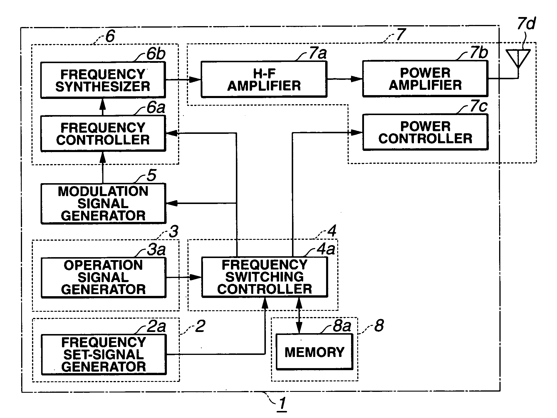
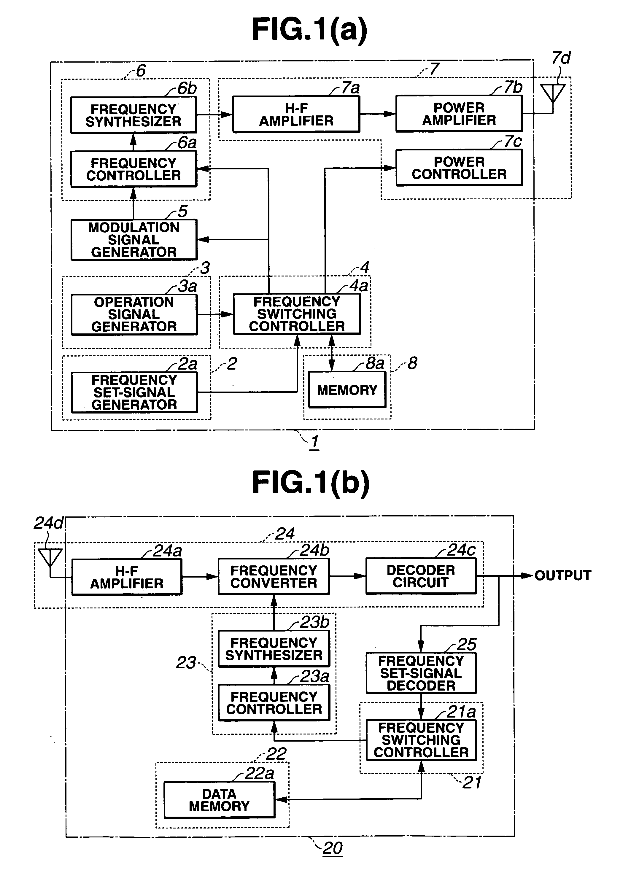
[0034]FIG. 1 is a block diagram illustrating a radio control system according to an embodiment of the present invention. FIG. 1(a) is a block diagram illustrating a transmitter and FIG. 1(b) is a block diagram illustrating a receiver.

[0035] The transmitter and the receiver are explained below respectively.

[0036] Transmitter:

[0037] In the embodiment of FIG. 1(a), the transmitter 1 includes frequency set signal generator means 2, operation signal generator means 3, frequency switching controller means 4, transmission frequency setting means 6, signal transmitter means 7, memory means 8, and modulation signal generator 5.

[0038] As shown in FIG. 1(a), the frequency set signal generator means 2 includes a frequency set signal generator 2a. The operation signal generator means 3 includes an operation signal generator 3a. The frequency switching con...


PUM


Abstract

In conventional radio controlled models, a receive frequency is changed with a changeover switch mounted in a receiver body. In the present invention, a frequency switching scheme, employing a radio system in which a transmitter switches the receive frequency, is provided. Using weak radio waves usable without authorization, the transmitter transmits frequency data set therein as a frequency switching signal to a receiver. In the receiver, the receive frequency is set to a predetermined weak radio wave frequency when the power source is turned on. Upon receiving the weak radio waves, the receiver reads the frequency data out of the set signal and stores it into the memory means. Thus, the frequency setting has been completed. When the receiver does not receive the frequency switching signal for a fixed period of time, it reads out the frequency data used previously from the data memory to start the receiving operation.

Description

BACKGROUND OF THE INVENTION [0001] The present invention relates to a radio control device (gear) for remotely manipulating radio controlled models. [0002] Nowadays, radio-control devices (hereinafter referred to as R / C device) are used for various radio controlled models (hereinafter referred to as R / C models) such as model aircraft, model helicopters, model vehicles, model boats and others. For them, two types of main carrier wave modulation scheme, that is, AM (Amplitude Modulation) and FM (Frequency Modulation) are used or two types of main carrier wave modulation signal conversion scheme, that is, PPM (Pulse Position Modulation) and PCM (Pulse Code Modulation) are used. [0003] Regarding the R / C devices, the frequency bands for carriers and frequencies in each frequency band, allowable in each country, are regulated by the Radio Law. For example, the frequency bands usable in Japan are 27 MHz band, 40 MHz band, and 72 MHz band, each in which plural frequencies are determined. [0...

Claims


Application Information

Patent Timeline
Patent Type & Authority Applications(United States)
IPC IPC(8): A63H19/24A63H30/04H04B1/04H04B1/06
CPCA63H19/24H04B17/391A63H30/04
Inventor YAMAMOTO, MICHIO
Owner YAMAMOTO MICHIO
Why Eureka
Try Eureka