Surgical device and method for pericardium retraction

a pericardium retraction and surgical device technology, applied in the field of surgical devices, can solve the problems of imposing loads and constraints on the beating heart, affecting the normal beating function of the heart, and inducing the onset of physiologically undesirable effects

Inactive Publication Date: 2005-08-04
PAOLITTO ANTHONY +2
View PDF14 Cites 29 Cited by
  • Summary
  • Abstract
  • Description
  • Claims
  • Application Information

AI Technical Summary

Problems solved by technology

One of the challenges in performing beating heart CABG surgery lies in positioning and orienting the beating heart in order to obtain access to the inferior and posterior artery beds, while aiming to minimize physiologically undesirable effects such as hemodynamic instability, arrhythmia, or a precipitous drop in arterial pressure, any of which may occur as a result of such beating heart manipulation.
Furthermore, a surgical device which enables manipulation of the beating heart or which restrains its movement or positioning may impose loads and constraints on the beating heart.
This may impede the normal beating function of the heart and induce the onset of the physiologically undesirable effects described above.
Consequently, because of this blind installation, the risk of unintentionally puncturing other underlying body tissue with the tissue piercing needle may lead to operative or postoperative complications, especially when a number of such sutures is required.
For instance, an inadvertent puncture of the pleura and lungs may lead to a pneumothorax injury if undetected.
The placement of deep pericardial traction sutures may therefore be challenging.
For example the placement of such sutures may be time consuming, since securing of the pericardium retraction load through the manual tying of the suture line lengths is often a multiple step threading and knotting procedure.
As well, the placement of pericardial traction sutures may in some instances be cumbersome due to poor access to the deeper portions of pericardial tissue and due to the number of traction sutures required to achieve beating heart “verticalization”.
Lastly, these sutures may not be conducive to permitting easy readjustment of the magnitude of the desired tensile load on the pericardium tissue, or of the direction of said load relative to the pericardium tissue.
Generally, adjustment of the desired tensile load on the pericardium tissue by cutting an existing suture line and repiercing a new suture line is not desirable.
First, the process of placing a pericardial traction suture requires considerable manual dexterity, at times requiring the help of an assistant.
The process is therefore tedious and time consuming.
Second, a repiercing of the pericardium tissue with a subsequent traction suture tends to increase the likelihood of inducing tissue trauma or tissue tearing which may have to be surgically repaired.
More specifically, the teachings of Benetti et al. result in immobilization of the pulsating effects of a portion of the exterior surface of the beating heart through negative force application at the target artery site.
However, in such a suggested device, if one suction port is not in contact with underlying tissue to form a seal, then the entire system will tend to be rendered ineffective, at least in part, by the leakage through said port.
Alternatively, Benetti et al. teach that each suction port can have it own independent supply line, which would circumvent this problem through a more complex, cumbersome, and part-intensive set-up.
If the suction is lost, the loss will lead to the surgical work-site of the beating heart no longer immobilized and resulting instability from pulsating effects.
If other instruments are in contact with the heart at this time, it may also lead to risk of trauma or injury.

Method used


Image

  • Surgical device and method for pericardium retraction
  • Surgical device and method for pericardium retraction
  • Surgical device and method for pericardium retraction

Examples


first embodiment

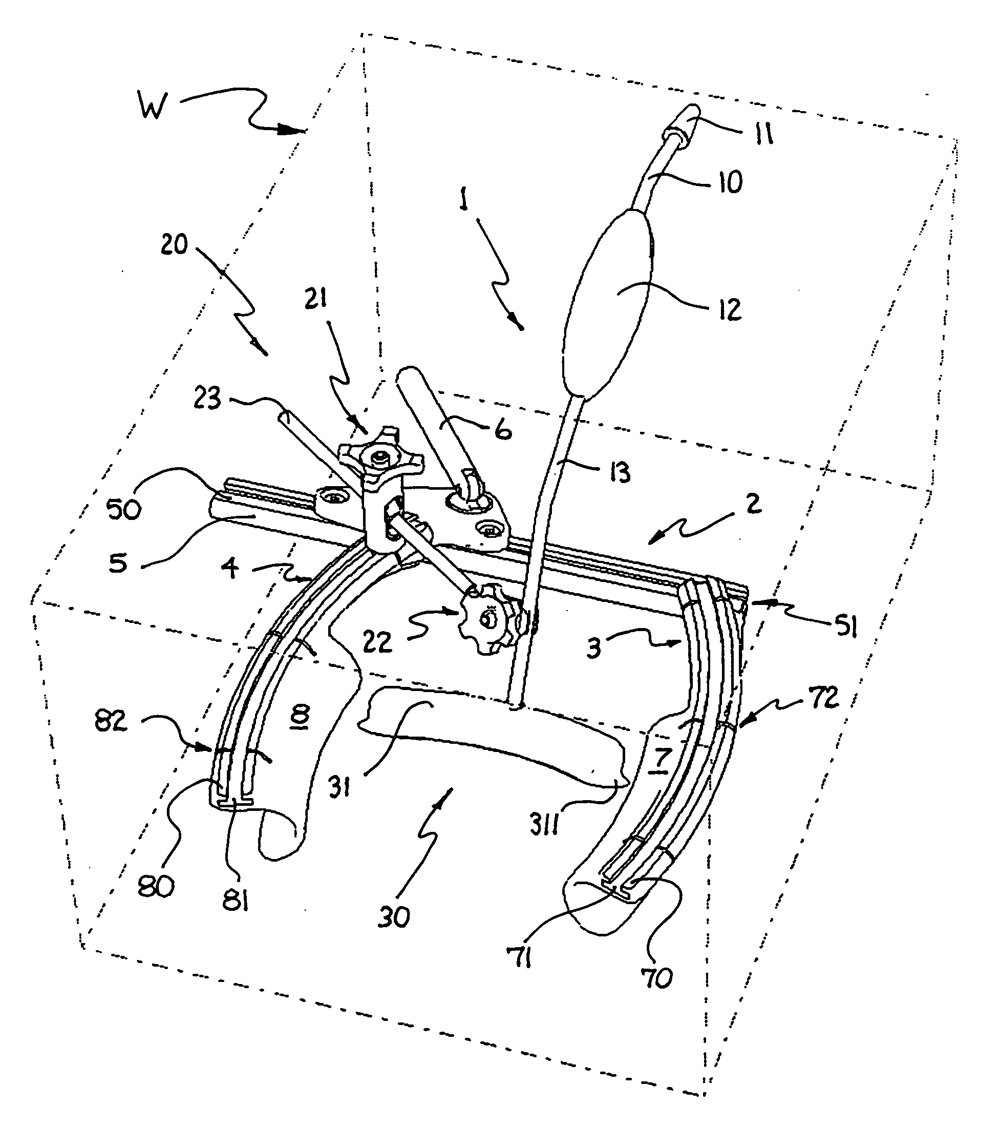
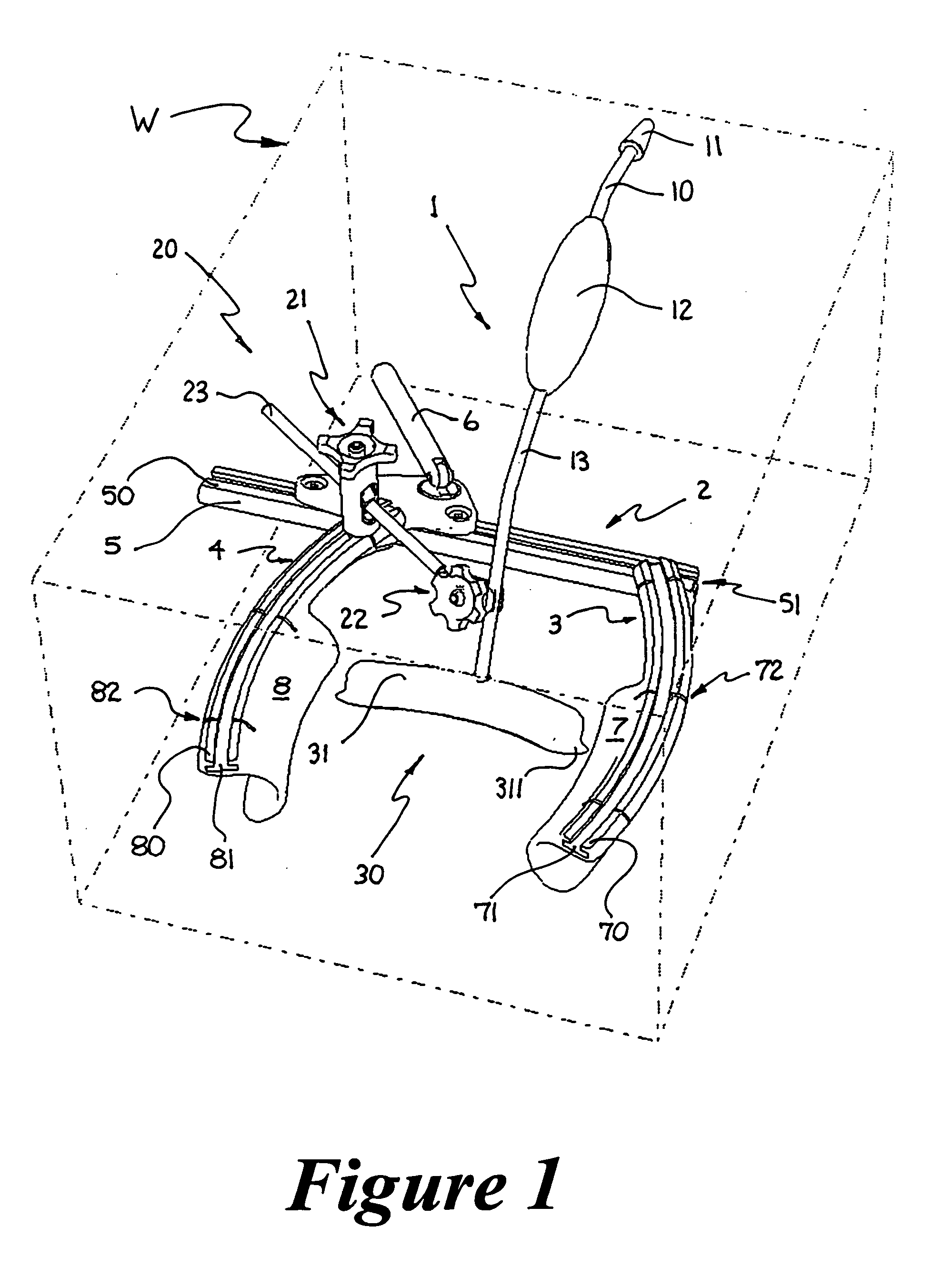
[0055] As further illustrated in FIG. 2, a pericardium retraction device 1 according to the present invention is comprised mainly of a tissue-engaging member 30, a device manipulating means such as shaft member 13, a conduit means such as conduit passage 10, and a suction line interface means such as pneumatic fitting 11. The tissue-engaging member 30 is of a substantially arcuate shape when viewed along the longitudinal axis of shaft member 13. It is further comprised of a substantially-elastic sheath 31 serving as an outer shell that is insertable over a substantially-rigid inner structure 32. Inner structure 32 is substantially air permeable. For instance the inner structure may be designed and produced with an open configuration structure, such as a perforated sheet structure or a truss-like space frame structure. Inner structure 32 is rigidly attached at one side thereof to shaft member 13 in the vicinity of source orifice 14, in either a permanent or demountable assembly. At a...

second embodiment

[0094] FIGS. 5 to 7 illustrate a second embodiment according to the present invention. The tissue-engaging member 130 of the pericardium retraction device 101 is comprised of a plurality of bell-shaped suction ports 36, each demountably attached to a substantially semicircular tubular spine 35 through an attachment fitting 351. This embodiment illustrates five such ports, which shall be referred to as ports A, B, C, D, and E in a clockwise direction. The suction ports 36 are described in greater detail below. The fittings 351 are preferably arranged such that their centerlines are substantially parallel to the centerline defining the semicircular tubular spine 35. Alternative embodiments may have attachment fittings351, and consequently suction ports 36, attached to spine 35 in a variety of orientations or combination of orientations. For example, ports A, C, and E may be configured with centerlines substantially parallel to the centerline defining semicircular spine 35, and ports B...

third embodiment

[0112] In this third embodiment, the tissue-engaging member 38 is comprised of a hollow attachment feature 388, a source orifice 141, a diaphragm member 387, and a spool valve means 380. The hollow attachment feature 388 serves to fixture said tissue-engaging member 38 to a substantially rigid tubular spine (like 35) in a plurality arrangement, or directly to a shaft member 13 in a single port arrangement. The source orifice 141 serves to communicate with the negative pressure source P2 through tubular spine (like 35) and conduit member 10. The diaphragm member 387 delimits a negative pressure plenum within tissue-engaging member 38.

[0113] The spool valve means 380 may assume either a “valve closed” position in which the negative pressure plenum P2 is delimited by diaphragm member 387, as illustrated in FIG. 9A, or an “open valve” position in which the negative pressure plenum is delimited by the engaged pericardium along perimeter 384, and as illustrated in FIG. 9B, the substantial...


PUM


Abstract

A surgical device and method for retracting a pericardium tissue, the surgical device having a tissue-engaging member for providing a negative pressure suction force to the pericardium tissue which is sufficient to retract same. The surgical device may be positioned in a retracting configuration wherein it provides a tensile load on the contacted portion of pericardium tissue thereby also positioning the patient's heart, that is anatomically attached to the pericardium tissue, within the thoracic cavity of the patient. The surgical device may be temporarily coupled to a surgical platform in its retracting configuration.

Description

FIELD OF THE INVENTION [0001] The present invention relates to the field of surgical apparatus and more specifically, to a tissue retraction device for positioning and orienting a beating heart during cardiac surgery. BACKGROUND OF THE INVENTION [0002] Coronary artery bypass graft (CABG) surgery is a widely practised surgical procedure for performing coronary artery revascularization or bypass grafts. This surgical procedure consists of replenishing or augmenting blood flow to a portion of the patient's heart which is being deprived of such flow due to a restriction or blockage in a coronary artery supplying the said portion of the patient's heart. A healthy segment from a blood vessel, such as an artery or a vein converted into an artery, is attached to the patient's vasculature from a point upstream of the coronary artery restriction or blockage to a point downstream thereof, thereby creating the bypass artery and associated bypass blood flow. Since the great majority of CABG surg...

Claims


Application Information

Patent Timeline
Patent Type & Authority Applications(United States)
IPC IPC(8): A61B17/02A61B17/30
CPCA61B17/02A61B17/0206A61B2017/308A61B2017/306A61B2017/0243
Inventor PAOLITTO, ANTHONYVALENTINI, VALERIOCARTIER, RAYMOND
Owner PAOLITTO ANTHONY
Why Eureka
Try Eureka