
Cardiac harness and method of delivery by minimally invasive access

a cardiac harness and minimally invasive technology, applied in the field of cardiac harnesses, can solve the problems of distressed cells, less able to deal with the stresses of expansion and contraction, and each hinge providing substantially unidirectional elasticity, so as to facilitate the delivery of cardiac harnesses and reduce the risk of cardiac arrest. the effect of affecting the cardiac rate and reducing the risk of cardiac arres

Inactive Publication Date: 2005-08-04
PARACOR MEDICAL INC
View PDF99 Cites 57 Cited by
  • Summary
  • Abstract
  • Description
  • Claims
  • Application Information

AI Technical Summary

Benefits of technology

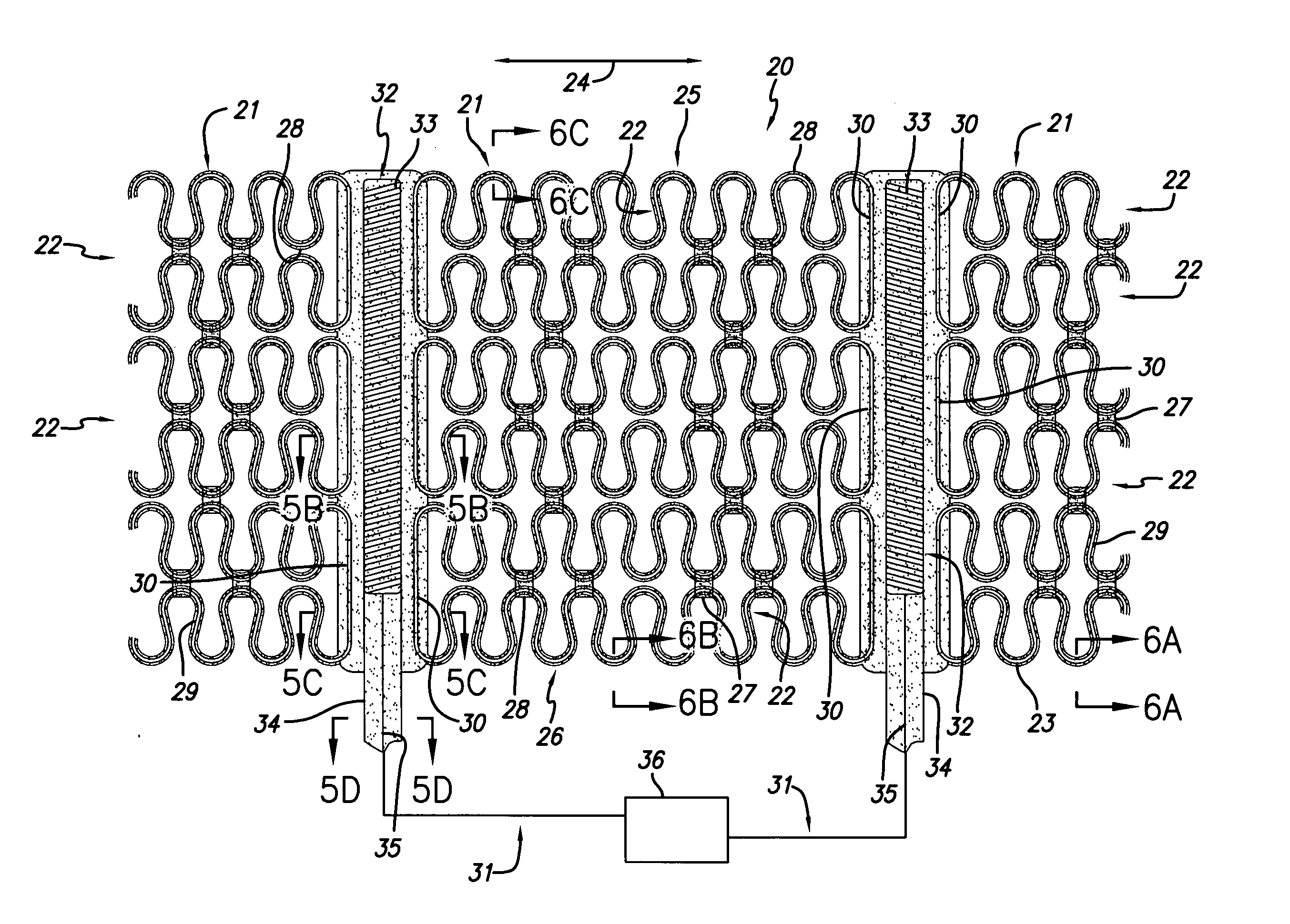
[0011] In another embodiment, the electrodes have a first surface and a second surface, the first surface being in contact with the outer surface of the heart, such as the epicardium, and the second surface faces away from the heart. Both the first surface and the second surface do not have a dielectric coating so that an electrical charge can be delivered to the outer surface of the heart for defibrillating or for pacing. In this embodiment, at least a portion of the electrodes are coated with a dielectric coating, such as silicone rubber, Parylene™ or polyurethane. The dielectric coating serves to insulate the bare metal portions of the electrode from the cardiac harness, and also to provide attachment means for attaching the electrodes to the panels of the cardiac harness.
[0016] In each of the embodiments, an electrical shock for defibrillation, or an electrical pacing stimuli for synchronization or pacing is delivered by a pulse generator, which can include an implantable cardioverter / defibrillator (ICD), a cardiac resynchronization therapy defibrillator (CRT-D), and / or a pacemaker. Further, in each of the foregoing embodiments, the cardiac harness can be coupled with multiple pacing / sensing electrodes to provide multi-site pacing to control cardiac function. By incorporating multi-site pacing into the cardiac harness, the system can be used to treat contractile dysfunction while concurrently treating bradycardia and tachycardia. This will improve pumping function by altering heart chamber contraction sequences while maintaining pumping rate and rhythm. In one embodiment, the cardiac harness incorporates pacing / sensing electrodes positioned on the epicardial surface of the heart adjacent to the left and right ventricle for pacing both the left and right ventricles.
[0020] In another embodiment, the cardiac harness includes coils that separate multiple panels. The coils have a high degree of flexibility, yet are capable of providing column strength to facilitate delivery of the cardiac harness by minimally invasive access.

Problems solved by technology

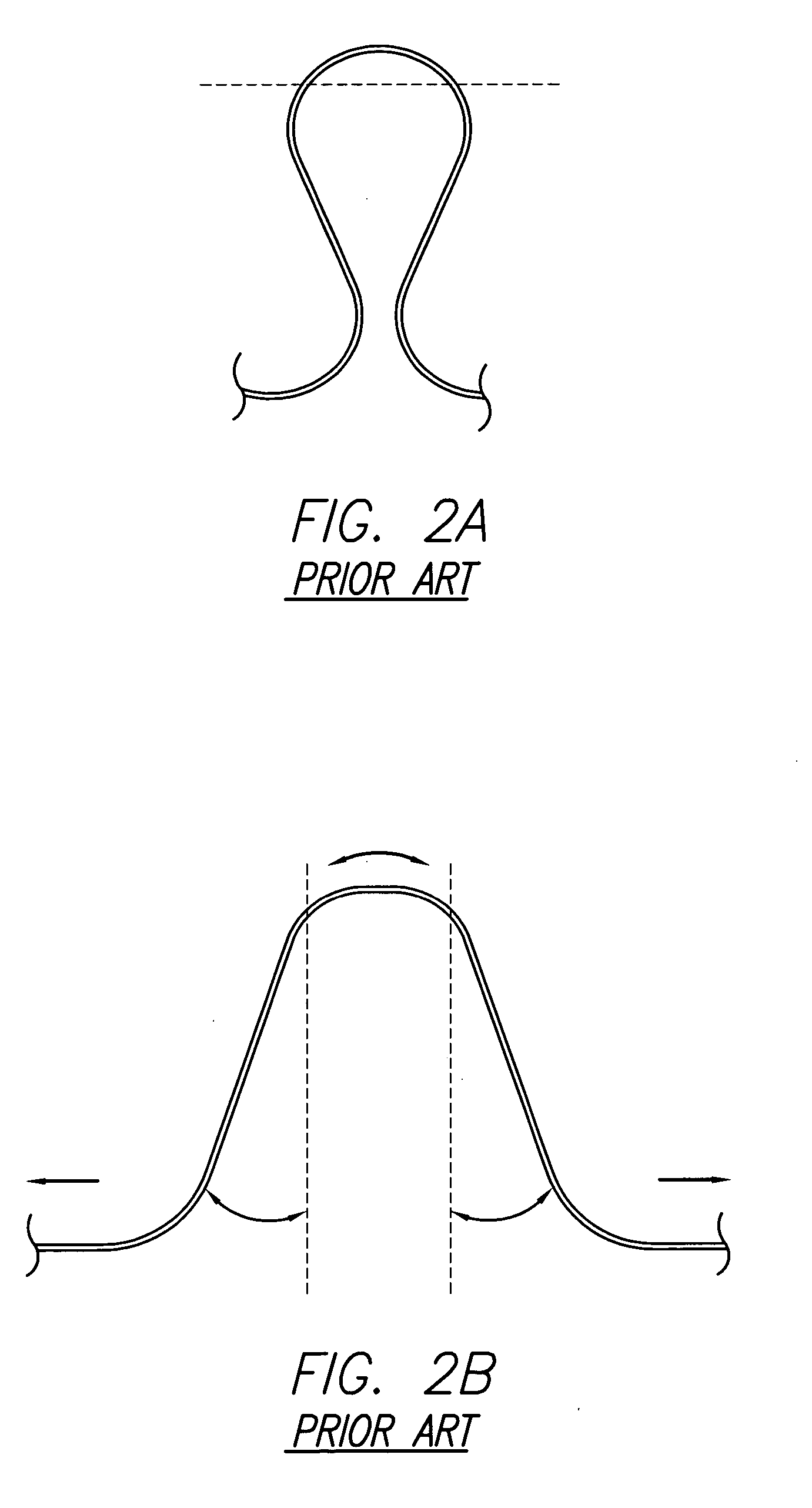
Each hinge provides substantially unidirectional elasticity, in that it acts in one direction and does not provide as much elasticity in the direction perpendicular to that direction.
In a diseased heart, the myocardium may expand such that the cells are distressed and lose at least some contractility.
Distressed cells are less able to deal with the stresses of expansion and contraction.
As such, the effectiveness of heart pumping decreases.
Other structural configurations for cardiac harnesses exist, however, but all have drawbacks and do not function optimally to treat CHF and other related diseases or failures.
One malady that is not uncommon is irregularity in heartbeat caused by irregularities in the electrical stimulation system of the heart.
For example, damage from a cardiac infarction can interrupt the electrical signal of the heart.
A problem with the heart's electrical system can sometimes cause the heart to fibrillate.
During fibrillation, the heart does not beat normally, and sometimes does not pump adequately.
Thus, the efficacy of defibrillation is reduced.
The dielectric material insulates the electrodes from the cardiac harness so that electrical current does not pass from the electrode to the harness thereby undesirably shunting current away from the heart for defibrillation.
While it is possible to remove the silicone rubber from only the second surface (facing away from the heart), and leaving the first surface coated with silicone rubber, an electrical shock can still be delivered from the bare metal second surface, however, the electrical shock delivered may not be as efficient as with other embodiments.

Method used


Image

  • Cardiac harness and method of delivery by minimally invasive access
  • Cardiac harness and method of delivery by minimally invasive access
  • Cardiac harness and method of delivery by minimally invasive access

Examples


Embodiment Construction

[0097] This invention relates to a method and apparatus for treating heart failure. It is anticipated that remodeling of a diseased heart can be resisted or even reversed by alleviating the wall stresses in such a heart. The present invention discloses embodiments and methods for supporting the cardiac wall and for providing defibrillation and / or pacing functions using the same system. Additional embodiments and aspects are also discussed in Applicants' co-pending application entitled “Multi-Panel Cardiac Harness” U.S. Ser. No. 60 / 458,991 filed Mar. 28, 2003, the entirety of which is hereby expressly incorporated by reference.

Prior Art Devices

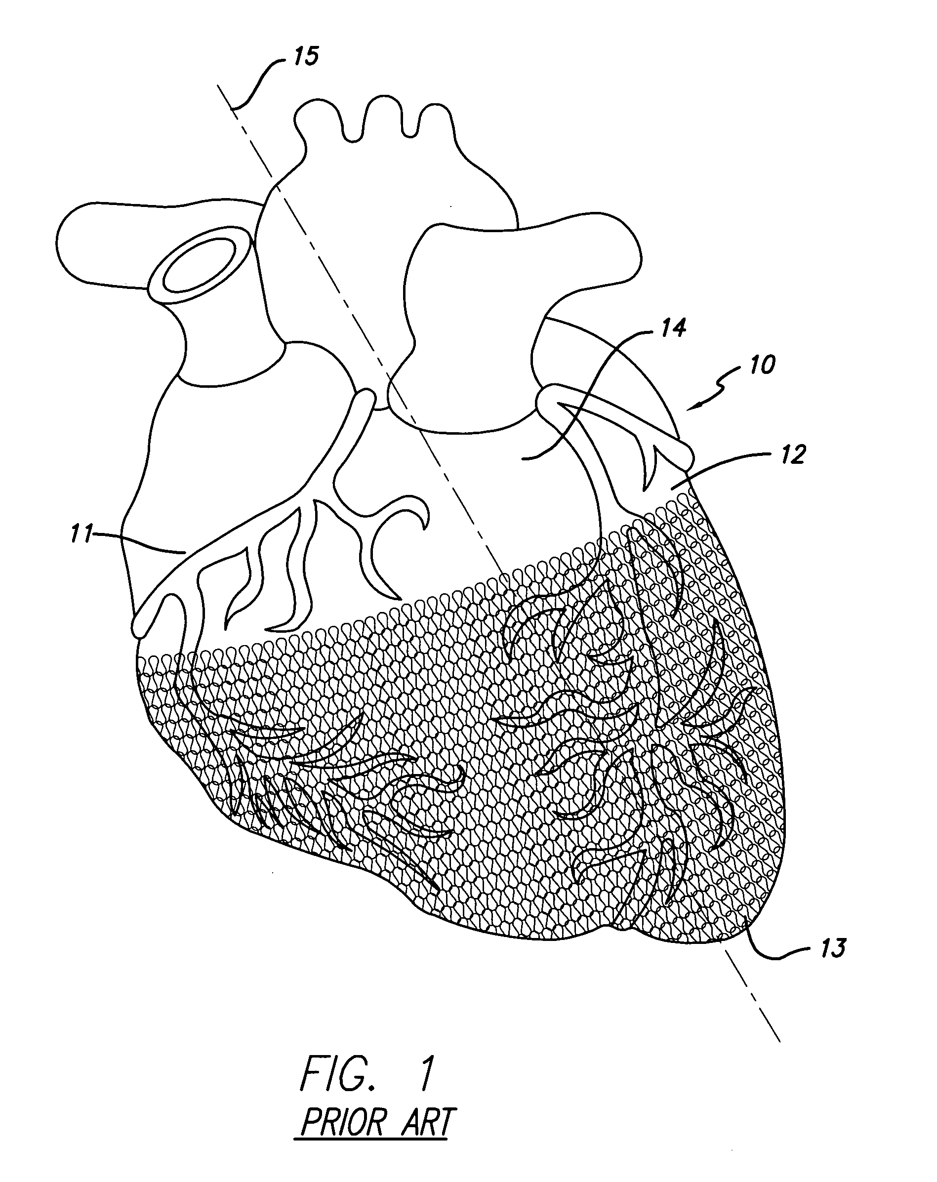
[0098]FIG. 1 illustrates a mammalian heart 10 having a prior art cardiac wall stress reduction device in the form of a harness applied to it. The harness surrounds a portion of the heart and covers the right ventricle 11, the left ventricle 12, and the apex 13. For convenience of reference, longitudinal axis 15 goes through the apex and the ...


PUM


Abstract

A system for treating the heart includes a cardiac harness associated with a cardiac rhythm management device which includes at least one electrode and a conductor lead that is connected to a power source. The electrodes include lumens for the removable insertion of a stylet or guide wire, which will provide the electrodes and the cardiac harness with the necessary columnar strength to push the cardiac harness over the heart. The stylet or guide wire also can be used to steer or lead the cardiac harness into position around at least a portion of the heart.

Description

CROSS-REFERENCE TO RELATED APPLICATION [0001] This application is a continuation-in-part of co-pending application Ser. No. 10 / 704,376 filed on Nov. 7, 2003, which is incorporated herein by reference.BACKGROUND OF THE INVENTION [0002] The present invention relates to a device for treating heart failure. More specifically, the invention relates to a cardiac harness configured to be fit around at least a portion of a patient's heart. The cardiac harness includes electrodes attached to a power source for use in defibrillation or pacing. [0003] Congestive heart failure (“CHF”) is characterized by the failure of the heart to pump blood at sufficient flow rates to meet the metabolic demand of tissues, especially the demand for oxygen. One characteristic of CHF is remodeling of at least portions of a patient's heart. Remodeling involves physical change to the size, shape and thickness of the heart wall. For example, a damaged left ventricle may have some localized thinning and stretching o...

Claims


Application Information

Patent Timeline
Patent Type & Authority Applications(United States)
IPC IPC(8): A61N1/05A61N1/375
CPCA61F2/2481A61N1/3756A61N1/0587A61F2002/2484
Inventor LAU, LILIPMAR, CRAIG
Owner PARACOR MEDICAL INC
Learn More