Digital filter design method and device, digital filter design program, and digital filter

a filter and design method technology, applied in the field of digital filter design methods and devices, digital filter design programs and digital filters, can solve the problems of difficult to set window functions or approximate expressions appropriately, not being able to easily design filters with desired characteristics, and not being able to obtain satisfactory frequency characteristics, etc., to prevent the generation of discretization errors in the filter coefficient obtained, reduce the number of circuit elements, and eliminate the use of window functions

Inactive Publication Date: 2005-08-04
NSC CO LTD
View PDF3 Cites 19 Cited by
  • Summary
  • Abstract
  • Description
  • Claims
  • Application Information

AI Technical Summary

Benefits of technology

[0019] As explained above, the present invention designs a digital filter by arbitrarily combining one or more unit filters having a predetermined asymmetric numerical sequence as filter coefficients, and can thereby automatically obtain coefficients of a digital filter having a desired frequency characteristic by only combining unit filters and allow even a non-expert technician to design a filter extremely simply.
[0020] Furthermore, according to the present invention, the above described asymmetric numerical sequence corresponds to one of two parts into which a predetermined symmetric numerical sequence is divided at the center and therefore requires only an extremely small number of taps necessary for the digital filter designed and require...

Problems solved by technology

However, the filter frequency characteristic obtained using the conventional design method depends on the window function or Chebyshev approximation, and therefore if these are not set properly, it is not possible to obtain a satisfactory frequency characteristic.
However, it is generally difficult to set a window function or approximate expression appropriately.
That is, the above described conventional filter design method requires a skilled technician to design the filter at much expense in time and effort and has a problem that it is not possible to design an FIR filter with a desi...

Method used


Image

  • Digital filter design method and device, digital filter design program, and digital filter
  • Digital filter design method and device, digital filter design program, and digital filter
  • Digital filter design method and device, digital filter design program, and digital filter

Examples


first embodiment

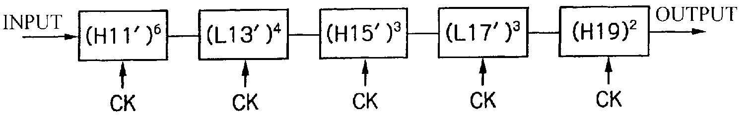
[0045] A filter design method according to a first embodiment allows an FIR filter having a desired frequency characteristic to be designed by only creating two types of 3-tap unit filters L1n′, H1n′ which will be explained below and combining them. The suffix “n” to each numeral indicating the unit filter denotes the number of clocks of a delay to be inserted between taps, that is, the number of “0”s to be inserted between filter coefficients (which will be explained in detail later).

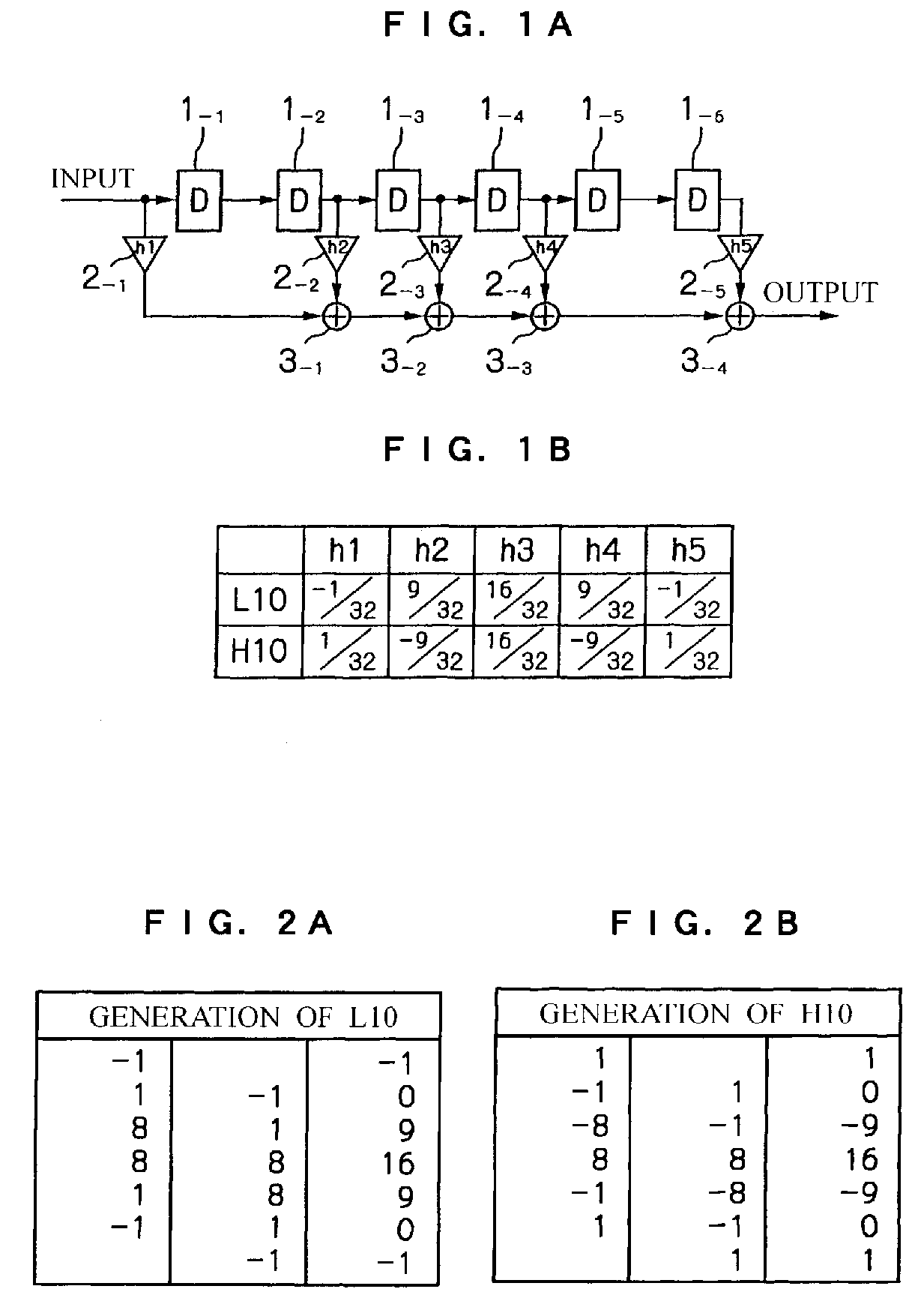
[0046] First, two types of 5-tap unit filters L1n, H1n which serve as a reference in understanding the above described two types of 3-tap unit filters L1n″, H1n′ will be explained. FIGS. 1A and 1B are diagrams showing the 5-tap unit filters L10, H10. FIG. 1A shows the circuit structure and FIG. 1B shows numerical sequences of filter coefficients.

[0047] As shown in FIG. 1A, the 5-tap unit filters L10, H10 delay an input signal sequentially by 1 clock CK at a time using six cascade-connected D-type fli...

second embodiment

[0112] A second embodiment of the present invention will be explained. In the above described first embodiment, as filter coefficients of the 3-tap low-pass unit filter L10′, those obtained by dividing a numerical sequence {−1, 0, 9, 16, 9, 0, −1} / 32 making up filter coefficients of the 5-tap low-pass unit filter L10 into two parts and then adjusting a numerical sequence {8, 9, 0, −1} / 16 which is one of them are used.

[0113] Furthermore, as filter coefficients of the 3-tap high-pass unit filter H10′ those obtained by dividing a numerical sequence {1, 0, −9, 16, −9, 0, 1} / 32 making up filter coefficients of the 5-tap high-pass unit filter H10 into two parts and then adjusting a numerical sequence {8, −9, 0, 1} / 16 which is one of them are used. Since filter coefficients of both of these 3-tap unit filters L10′, H10′ are of an asymmetric type, phase linearity is not guaranteed as described above.

[0114] In contrast, the second embodiment is designed to realize a linear phase characteri...


PUM


Abstract

A digital filter is designed by combining unit filters (L10′, H10′) having a predetermined asymmetric numerical sequence as filter coefficients (H1 to H3). Thus, it is possible to automatically obtain a desired digital filter coefficient only by combining the unit filter. Moreover, a symmetric numerical sequence {−1, 0, 9, 16, 9, 0, −1}/32 is divided at the center into two parts and one of them is used as the asymmetric filter coefficients (H1 to H3). This reduces the number of taps required for the digital filter designed, eliminates use of a window function, and prevents generation of a discretization error in the filter characteristic obtained.

Description

BACKGROUND OF THE INVENTION [0001] 1. Field of the Invention [0002] The present invention relates to a digital filter designing method and device, digital filter designing program and digital filter, and more particularly, to an FIR filter and a method of designing it, which comprises a tapped delay line made up of a plurality of delayers and performs multiplying signals of the respective taps several-fold and then adding up the results of multiplication and outputting the addition result. [0003] 2. Description of the Related Art [0004] Some kind of digital signal processing is generally performed in various kinds of electronic devices provided in various fields of communication, measurement, sound / image signal processing, medical care, seismology, and so on. One of the most significant basic operation of the digital signal processing is filtering which extracts only a signal having a necessary frequency band from an input signal in which signal and noise are mixed. For this reason,...

Claims


Application Information

Patent Timeline
IPC IPC(8): G06F17/10H03H17/02H03H17/06
CPCH03H17/0229H03H2017/0072H03H17/06
Inventor KOYANAGI, YUKIO
Owner NSC CO LTD
Why Eureka
Try Eureka