Method and apparatus for reducing segregation in metallic ingots

a technology of segregation and ingots, which is applied in the direction of manufacturing tools, moulding machines, and foundation moulding apparatus, etc., can solve the problems of reducing the life of low cycle fatigue (lcf) products, exhibiting significant macro-segregation defects in the ingots produced by esr from such alloys, and reducing the size of the ingot produced by esr, etc., to achieve the effect of reducing macro-segregation

Inactive Publication Date: 2005-08-11
ATI PROPERTIES
View PDF3 Cites 15 Cited by
  • Summary
  • Abstract
  • Description
  • Claims
  • Application Information

AI Technical Summary

Benefits of technology

[0016] The various methods and apparatus disclosed herein may be used to reduce macro-segregation in certain segregation-prone metallic alloys, although use of the methods and apparatus are not so restricted. Non-limiting examples of metallic alloys it is believed may be processed using the methods and apparatus described herein include certain iron-, nickel-, and cobalt-base alloys, including certain nickel-base superalloys such as alloy 718.

Problems solved by technology

However, larger diameter ingots produced by ESR from such alloys have exhibited significant macro-segregation defects.
Thus, while products made from alloy regions having a desired chemistry may exhibit sufficient mechanical properties for the intended application, products including alloy regions containing macro-segregation defects may not have acceptable mechanical properties.
For example, alloy regions affected by macro-segregation may be more likely to have lower ductility and elongation properties and lower Low Cycle Fatigue (LCF) life, which could result in premature part failure.
However, alloys produced in this way may include oxide clusters, which can produce flaws in products made from the alloys.
Such flaws can also result in low ductility and premature part failure.
Conventional ESR also has been used as the final melt process to produce large diameter ingots, but the results generally have been unsatisfactory.
While use of ESR can avoid the oxide cluster problems experienced with VAR, large diameter ingots made of segregation-prone alloys processed using conventional ESR as the final melt process often exhibit severe macro-segregation.

Method used


Image

  • Method and apparatus for reducing segregation in metallic ingots
  • Method and apparatus for reducing segregation in metallic ingots
  • Method and apparatus for reducing segregation in metallic ingots

Examples


Embodiment Construction

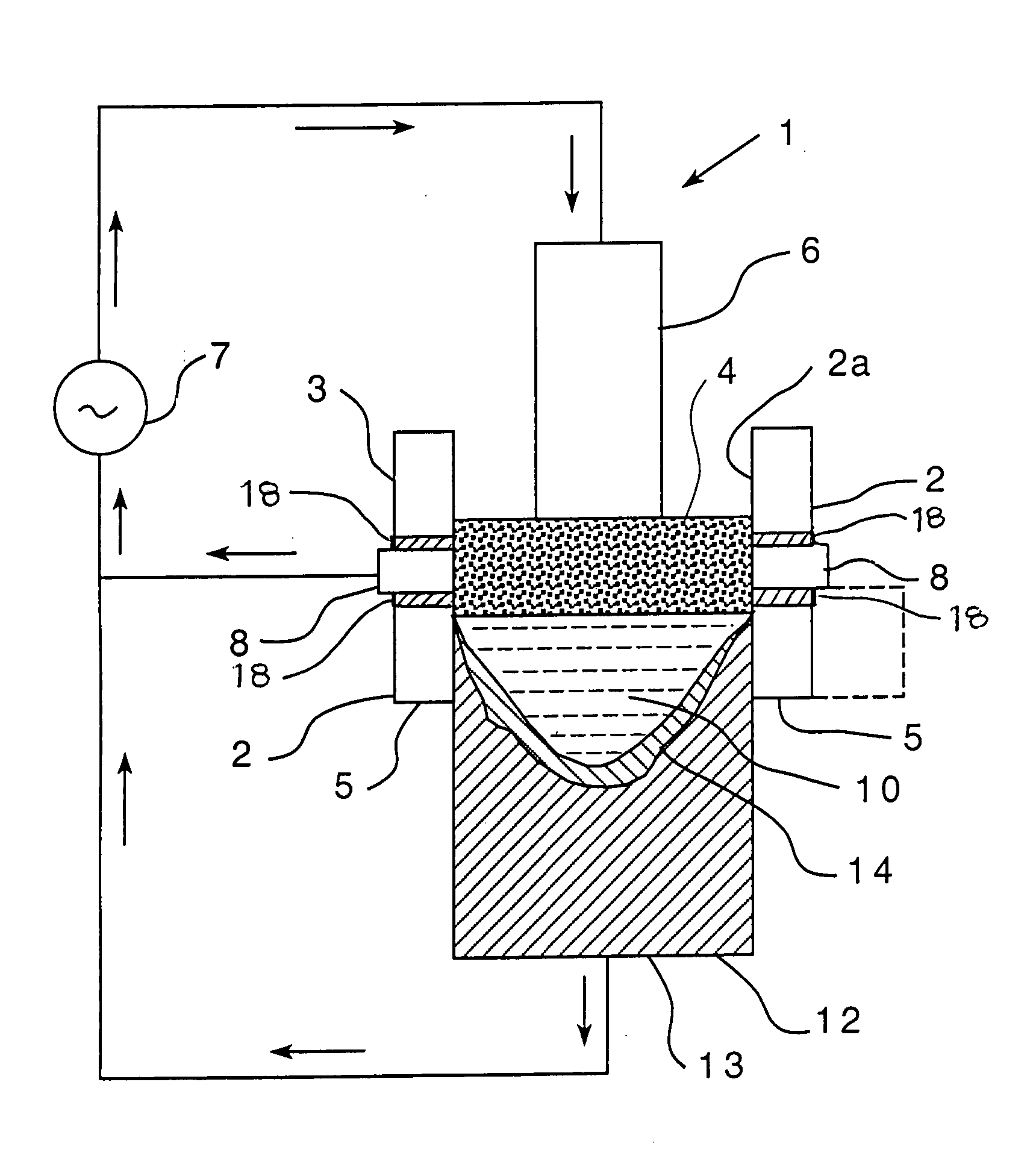
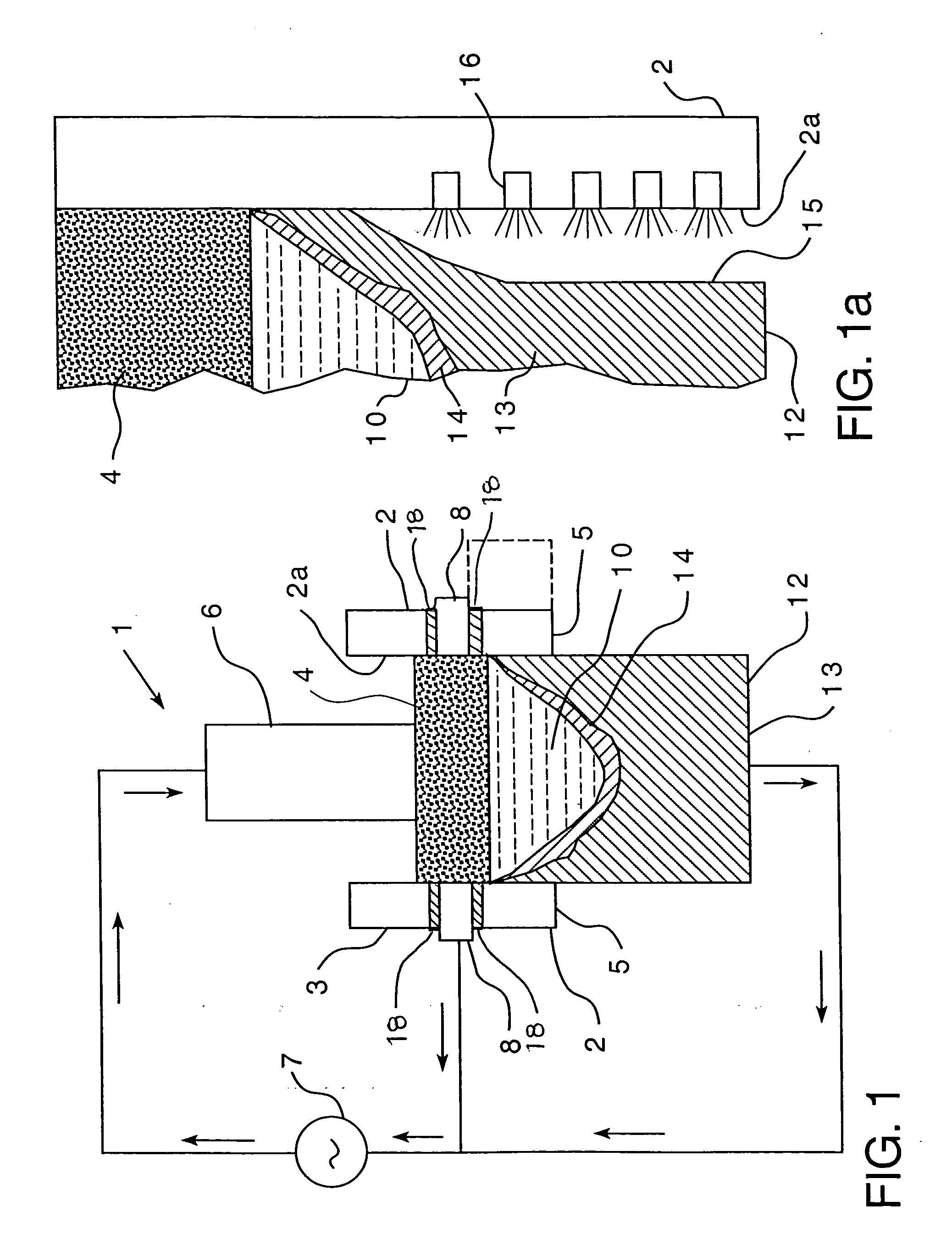
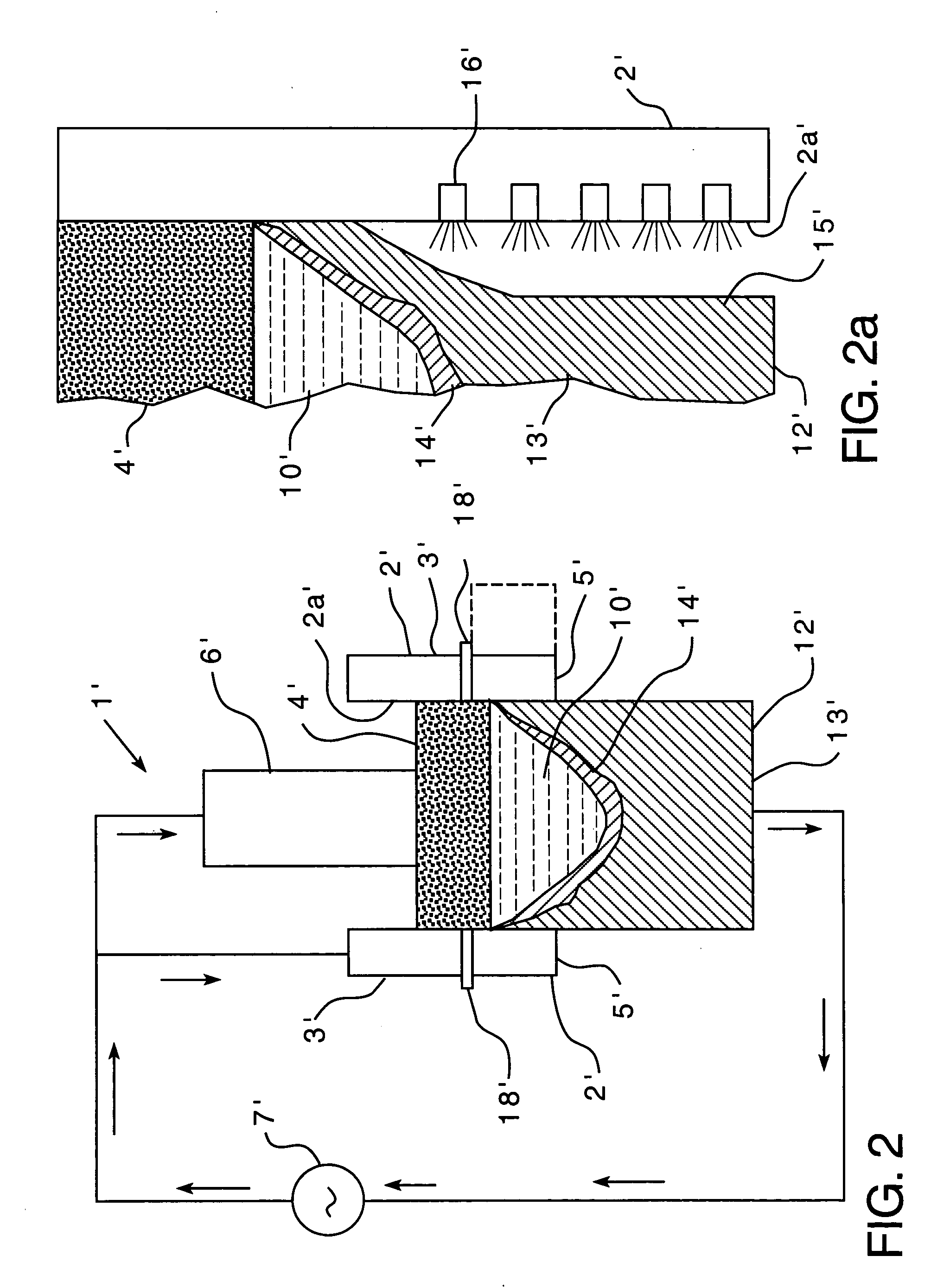
[0022] Each of the non-limiting embodiments described herein is believed to be useful in the manufacture of large diameter ingots of metallic (i.e., metal-containing) alloys, wherein use of conventional ESR methods would result in macro-segregation within the ingot. It will be understood, however, that the use of the embodiments described herein is not so limited, and the embodiments may be employed in, for example, the production of metallic ingots of any size, including large diameter ingots. As noted above, as used herein, “large diameter” refers to diameters greater than 16 inches (about 0.40 m). Thus, for example, and without limiting the present disclosure in any way, ingots having diameters of 20 inches (about 0.508 m) and 38 inches (about 0.965 m) may be made according to methods disclosed herein. Also, as used herein, “metallic ingot” and “metallic alloy” refer to, respectively, an ingot and an alloy that are at least partially composed of metal.

[0023] By way of example on...


PUM

PropertyMeasurementUnit
diameteraaaaaaaaaa
diameteraaaaaaaaaa
diametersaaaaaaaaaa

Abstract

The present disclosure relates to electroslag remelting methods and apparatus for producing metallic ingots, as well as to articles of manufacture made from materials processed according to the methods and/or using the apparatus. One such method includes disposing slag within a withdrawal mold comprising a mold wall and an electrically conductive member disposed through the mold wall, contacting the slag with a consumable electrode, and heating the slag by conducting an electrical current through the consumable electrode into the slag, thereby melting at least a portion of the consumable electrode in contact with the slag. At least a fraction of the melted portion of the consumable electrode is collected in the withdrawal mold to form the ingot. At least a portion of the electrical current is conducted form the slag through the electrically conductive member.

Description

BACKGROUND OF THE TECHNOLOGY [0001] 1. Field of Technology [0002] The present disclosure relates to methods and apparatus for producing metallic ingots, as well as to articles of manufacture made from materials processed according to the methods and / or using the apparatus. [0003] 2. Description of the Background of the Technology [0004] Specialty alloys are often used in applications where high performance characteristics are of paramount importance. Such applications include: high strength components for jet engines made from forgings, castings, and bar stock; cryogenic and liquid fuel rocket components, such as engines, nozzles, and combustion components; FGD systems; nuclear and chemical processing industry (CPI) pumps; land based turbine wheels, spacers, turbine compressor blades and discs; parts for steam and gas turbines; cutting tools; airframe structural parts; valve parts; and chemical process equipment. Because of the demanding nature of these and other high performance ap...

Claims


Application Information

Patent Timeline
Patent Type & Authority Applications(United States)
IPC IPC(8): B22D23/10C22B9/18
CPCB22D23/10
Inventor KENNEDY, RICHARD L.JACKMAN, LAURENCE A.MINISANDRAM, RAMESH S.FORBES JONES, ROBIN M.BALLANTYNE, ALEXANDER S.
Owner ATI PROPERTIES
Why Eureka
Try Eureka