Stacking-type, multi-flow, heat exchanger
a heat exchanger and multi-flow technology, applied in the direction of lighting and heating apparatus, stationary conduit assemblies, laminated elements, etc., can solve the problems of insufficient brazing strength and improper connection of respective parts, and achieve high degree of accuracy in position, sufficient bonding strength, and high degree of accuracy
- Summary
- Abstract
- Description
- Claims
- Application Information
AI Technical Summary
Benefits of technology
Problems solved by technology
Method used
Image
Examples
first embodiment
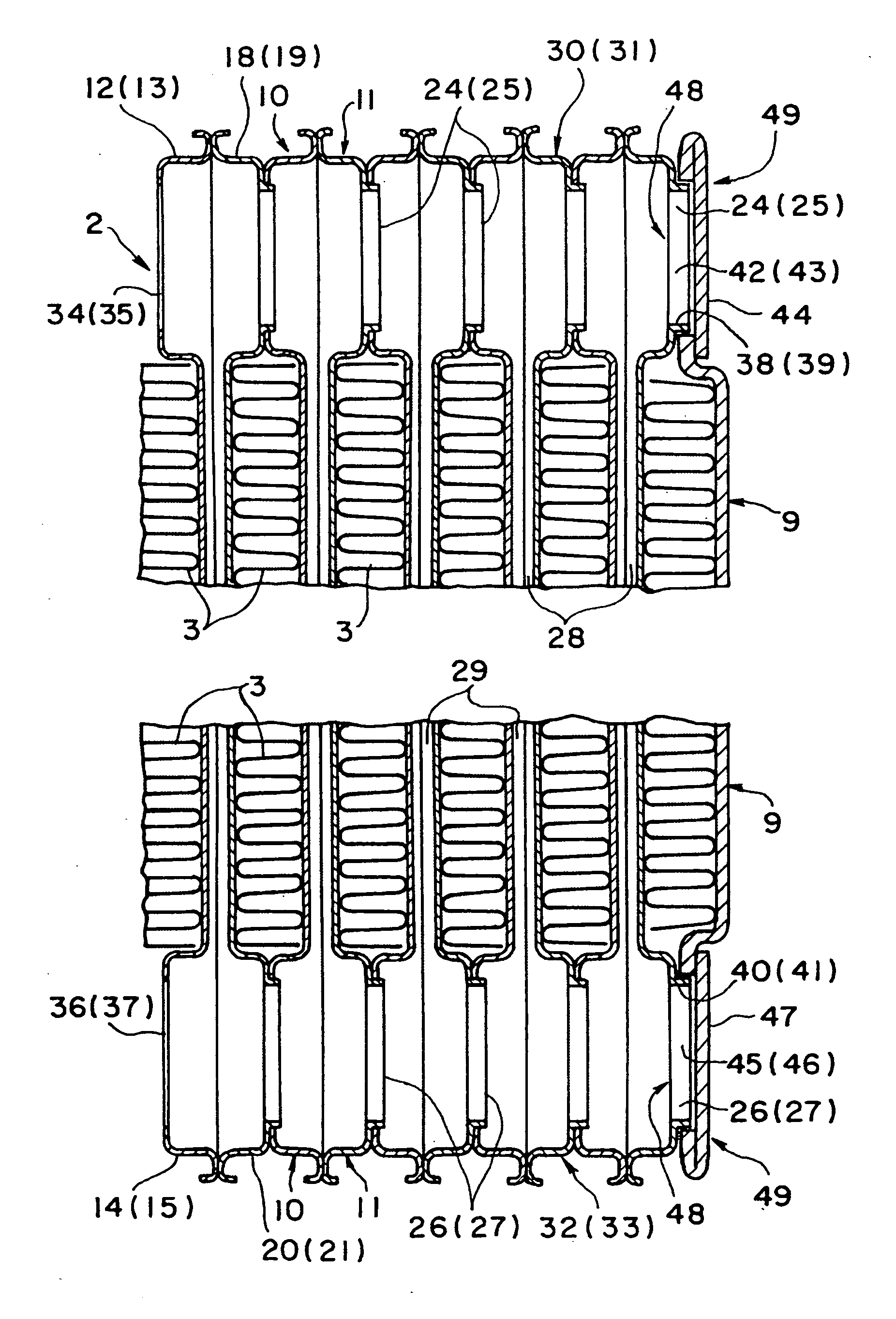
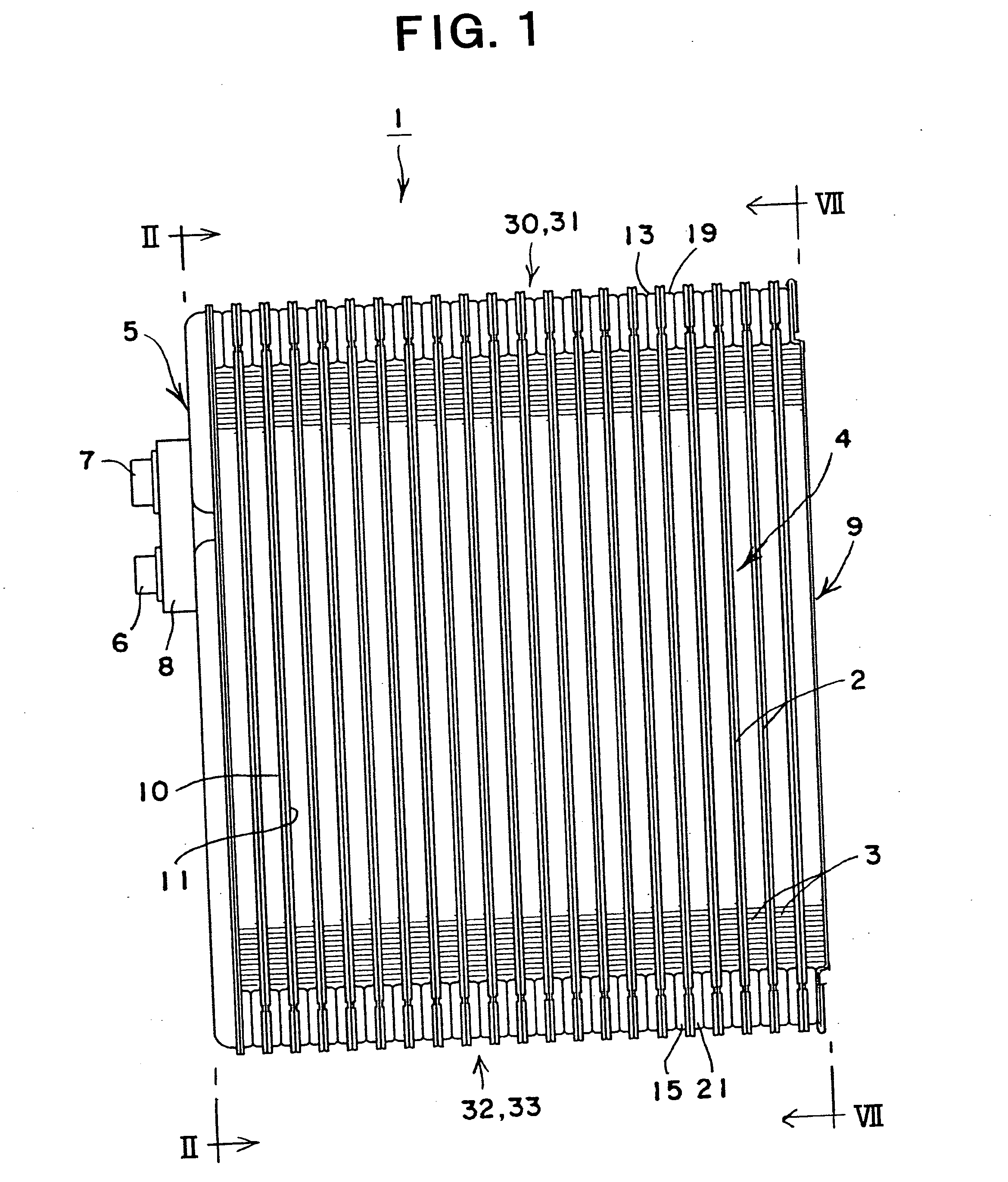
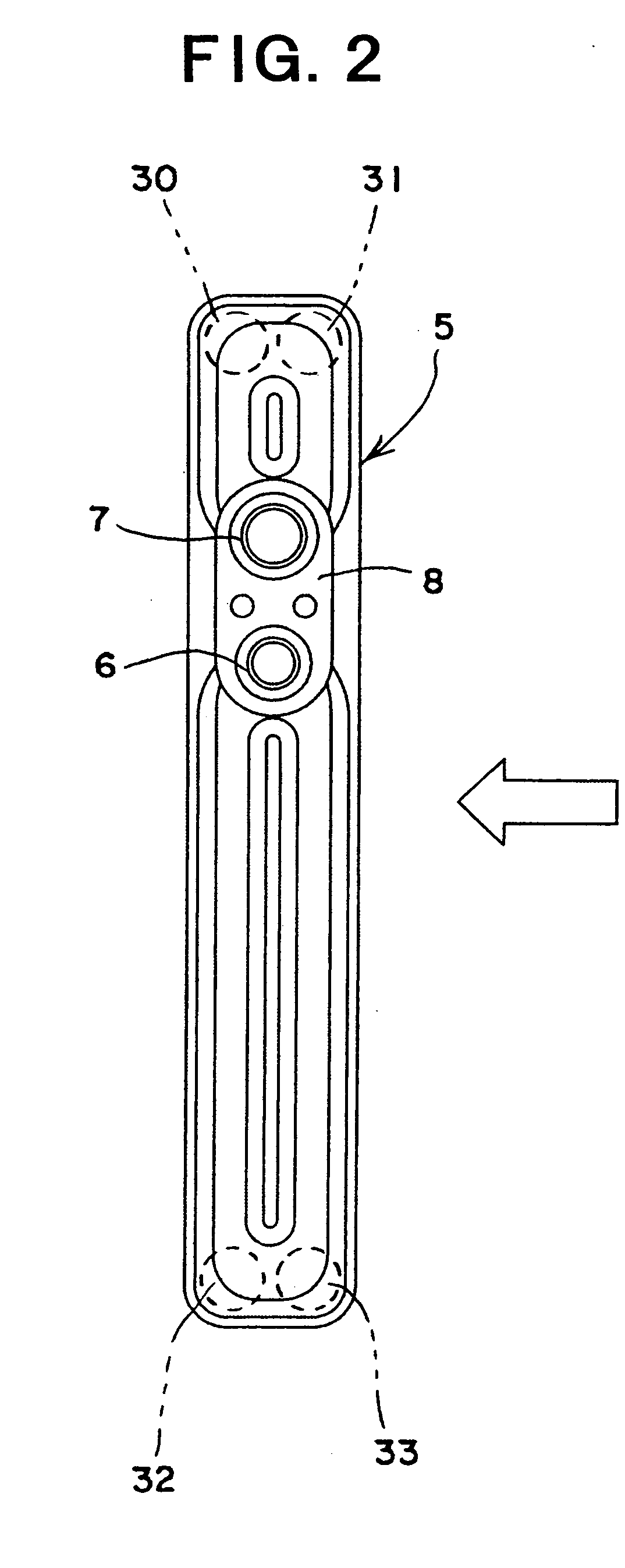
[0046] Referring to FIGS. 1-7, a heat exchanger is depicted according to the present invention. Heat exchanger 1 is constructed as a stacking-type, multi-flow, heat exchanger. As depicted, heat exchanger 1 comprises a heat exchanger core 4 formed by a plurality of heat transfer tubes 2 and a plurality of outer fins 3 stacked alternately. A side tank 5 is connected to one end of heat exchanger core 4 in the stacking direction, and introduction / discharge passages of a heat exchange medium (e.g., refrigerant) into / from the heat exchanger are formed in the side tank 5. A flange 8 having an inlet 6 and an outlet 7 for heat exchange medium is connected to side tank 5. An end plate 9 is connected to the other end of heat exchanger core 4 in the stacking direction.
[0047] As depicted in FIGS. 3 and 5, each heat transfer tube 2 is formed by connecting a pair of tube plates 10 and 11 (i.e., a first tube plate 10 and a second tube plate 11) to each other at their outer circumferential portions....
third embodiment
[0059] FIGS. 13 to 16 depict a stacking-type, multi-flow, heat exchanger and the method for manufacturing such a heat exchanger, according to the present invention. In this embodiment, as depicted in FIG. 14, lid forming portions 63a and 64a are formed integrally with end plate 62 at both end portions of end plate 62 in its longitudinal direction. Protruded portions 65, 66, 67, and 68 are formed on lid forming portions 63a and 64a, respectively. As depicted in FIGS. 15A and 15B, by turning back lid forming portions 63a and 64a, lids 63 and 64 are formed, and the lids 63 and 64 cover holes 69, 70, 71, and 72 provided on end plate 62, respectively, as depicted in FIG. 16.
[0060] Moreover, in this embodiment, because raised portions 24, 25, 26, and 27 of second tube plate 11 are inserted into holes 69, 70, 71, and 72 of end plate 62, respectively, end plate 62 may be positioned with a high degree of accuracy similar to that in the first embodiment, and the brazing properties may be impr...
PUM
 Abstract
Description
Claims
Application Information
 - R&D
- Intellectual Property
- Life Sciences
- Materials
- Tech Scout
- Unparalleled Data Quality
- Higher Quality Content
- 60% Fewer Hallucinations
Browse by: Latest US Patents, China's latest patents, Technical Efficacy Thesaurus, Application Domain, Technology Topic, Popular Technical Reports.
© 2025 PatSnap. All rights reserved.Legal|Privacy policy|Modern Slavery Act Transparency Statement|Sitemap|About US| Contact US: help@patsnap.com


