Liquid crystal display apparatus

a technology of liquid crystal display and display circuit, which is applied in the direction of liquid crystal compositions, chemistry apparatus and processes, instruments, etc., can solve the problems of giving the user unpleasant feelings, and achieve the effects of low cost, simplified driving circuit, and high accuracy display

Inactive Publication Date: 2005-08-11
KONICA MINOLTA INC
View PDF2 Cites 15 Cited by
  • Summary
  • Abstract
  • Description
  • Claims
  • Application Information

AI Technical Summary

Benefits of technology

[0019] The liquid crystal display apparatus according to the present invention further comprises scanning electrodes and signal electrodes which face each other with the liquid crystal layer in-between, and the driving section comprises a scanning electrode driving circuit for applying a reset pulse in the reset step, a selection pulse in the selection step and an evolution pulse in the evolution step to the scanning electrodes, and a signal electrode driving circuit for applying a signal pulse, which is of a volta...

Problems solved by technology

Therefore, every time the display is updated; the screen becomes dark, that is, a ...

Method used


Image

  • Liquid crystal display apparatus
  • Liquid crystal display apparatus
  • Liquid crystal display apparatus

Examples


first embodiment

; See FIG. 5

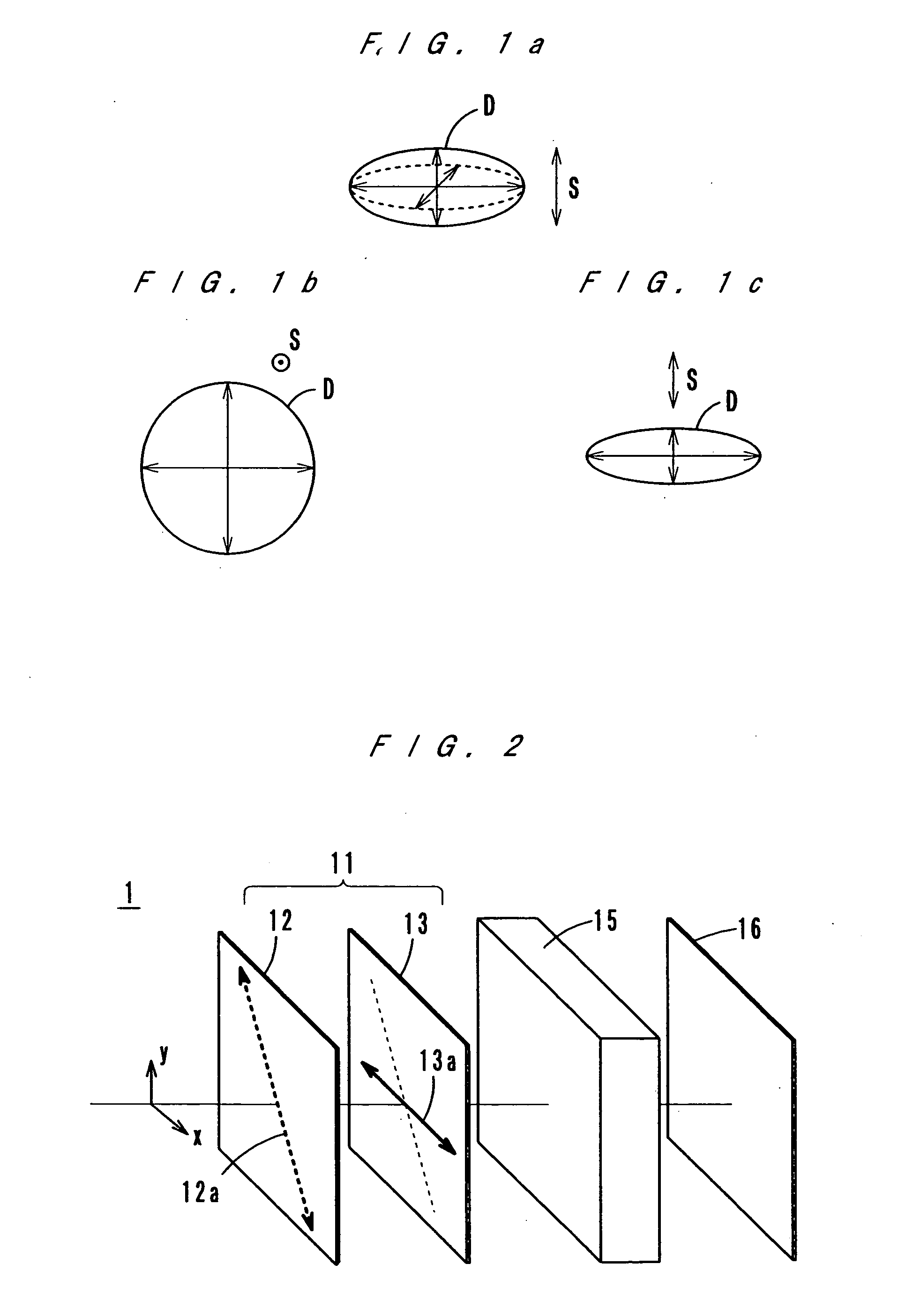
[0047] As FIG. 5 shows, a liquid crystal display apparatus 1A according to a first embodiment of the present invention comprises a circular polarizer 11 (composed of a linear polarizer 12 and a retardation film 13) and a liquid crystal display 15 which are stacked in this order from an observing side.

[0048] The liquid crystal display 15 has chiral nematic liquid crystal between substrates 51 and 52. The substrate 51 by the side of the observing surface is made of a transparent material with a high transmittance, and the substrate 52 on the back may be transparent or opaque. As the material of the substrates 51 and 52, a thin glass plate and a film of resin, such as polyether sulfone (PES), polycarbonate (PC), polyethylene terephthalate (PET), etc., are usable. On the mutually opposite sides of the substrates 51 and 52, electrodes 53 and 54 and aligning layers 55 and 56 are formed. In addition to the aligning layers 55 and 56, insulating layers may be formed. Although th...

second embodiment

; See FIG. 6

[0068]FIG. 6 shows a liquid crystal display 1B according to a second embodiment of the present invention. The liquid crystal display 1B is basically of the structure of the liquid crystal display 1A according to the first embodiment of the present invention. The liquid crystal display 1B further comprises a scattering layer 14 between the circular polarizer 11 and the liquid crystal display 15.

[0069] Although the scattering layer 14 is not indispensable, it is provided to achieve a good white display. The scattering layer 14 is a transparent material with particles of different refractive indexes scattered therein. The scattering layer 14 may be a film or may be a sticky film. As the transparent material, polyeter sulfone (PES), polycarbonate (PC), triacetyl cellulose (TAC), etc. are usable. As the particles, spherical particles of acrylic resin, silica, etc. are usable. Also, it is possible to give a scattering function to a transparent plate by roughening a surface of...

third embodiment

; See FIGS. 7a and 7b

[0073] Although the above-described liquid crystal display apparatuses 1A and 1B are of a reflective type, the present invention is applicable to any liquid crystal display apparatus as long as it makes a display by controlling light emergent from a liquid crystal layer via a circular polarizer located by the observing side of the liquid crystal layer. For example, the present invention is also applicable to a light-transmitting type liquid crystal display apparatus which has a light source at the side opposite the observing side. FIGS. 7a and 7b show an example of this type of liquid crystal display apparatus.

[0074] Compared with the above-described liquid crystal display apparatus 1A, in the light-transmitting type liquid crystal display apparatus 1C, the lower electrodes are not reflective electrodes and are transparent electrodes 54′, and a second circular polarizer 11′ and a backlight 60 are further provided in the lowest section. The axes of polarization...


PUM


Abstract

A liquid crystal display apparatus which have a circular polarizer and a liquid crystal display in a stack. The liquid crystal display has a chilral nematic liquid crystal layer between substrates, and on the mutually opposite sides of the substrates, electrodes and aligning layers are formed. The liquid crystal switches between a planar alignment state and a focal-conic alignment state depending on the voltage applied thereto through the electrodes. In a planar state, light reflected by the electrodes is absorbed by the circular polarizer, and a black display is made. In a focal-conic state, light reflected by the electrodes passes through the circular polarizer, and a white display is made. The liquid crystal is driven by a chain of voltage pulses including a reset step of resetting the liquid crystal to a homeotropic state, a selection step of selecting the alignment state of the liquid crystal under zero-volt application and an evolution step of causing the liquid crystal to evolve to the selected alignment state.

Description

[0001] This application is based on Japanese patent application No. 2004-34309 filed on Feb. 10, 2004, the content of which is hereby incorporated by reference. BACKGROUND OF THE INVENTION [0002] 1. Field of the Invention [0003] The present invention relates to a liquid crystal display apparatus, and more particularly to a liquid crystal display apparatus which uses cholesteric liquid crystal as a display medium. [0004] 2. Description of Related Art [0005] In recent years, reflective type liquid crystal displays are studied and developed into displays of mobile telephones and portable personal computers. Reflective type liquid crystal displays make displays by reflecting external light and therefore are advantageous of being power-saving, of being thin and light, etc. [0006] In reflective type liquid crystal displays, generally, nematic liquid crystal is used, and these liquid crystal displays are operated typically in a TN (twisted nematic) mode and in an STN (super twisted nematic...

Claims


Application Information

Patent Timeline
IPC IPC(8): G02F1/133G02F1/137G09G3/20G09G3/36
CPCG02F1/13718G09G3/3629G09G2320/02G09G2310/06G09G2300/0486
Inventor IZUMI, TOMOOMIYAI, MITSUYOSHIYAMADA, JUNOKADA, MASAKAZUFURUKAWA, KEIICHI
Owner KONICA MINOLTA INC
Why Eureka
Try Eureka