
High resolution ink jet printhead

a printhead and high-resolution technology, applied in the field of ink jet printheads, can solve the problems of limiting the high-frequency operation of the ejector actuator, quality defects, and the evolution of the printhead, and achieve the effect of increasing the size of the printhead components and increasing the print resolution

Active Publication Date: 2005-08-11
SLINGSHOT PRINTING LLC
View PDF23 Cites 11 Cited by
  • Summary
  • Abstract
  • Description
  • Claims
  • Application Information

AI Technical Summary

Benefits of technology

[0007] An advantage of the invention is that it provides printheads having increased print resolution without decreasing the firing frequency and without significantly increasing the size of the printhead components. The invention also enables production of printheads having a nozzle pitch of greater than 600 dpi without the need to provide adjacent nozzles and corresponding ink chambers that are offset from one another in a direction orthogonal to the ink feed slot. Accordingly, the fluidic characteristics of each of nozzles are substantially the same.
[0008] For purposes of this invention, the term “pitch” as it is applied to nozzles or ink ejection actuators is intended to mean a center to center spacing between adjacent nozzles or ejection actuators in a direction substantially parallel with an axis aligned with a columnar nozzle array. The term “aspect ratio” as it applies to the ink ejection actuators is the ratio of the length of the actuators to the width of the actuators.

Problems solved by technology

As the capabilities of ink jet printers are increased to provide higher quality images at increased printing rates, printheads, which are the primary printing components of ink jet printers, continue to evolve and become more complex.
Such a design results in adjacent nozzles having different fluidic characteristics such as refill times which can result in quality defects and can limit high frequency operation of the ejector actuators.

Method used


Image

  • High resolution ink jet printhead
  • High resolution ink jet printhead
  • High resolution ink jet printhead

Examples


Embodiment Construction

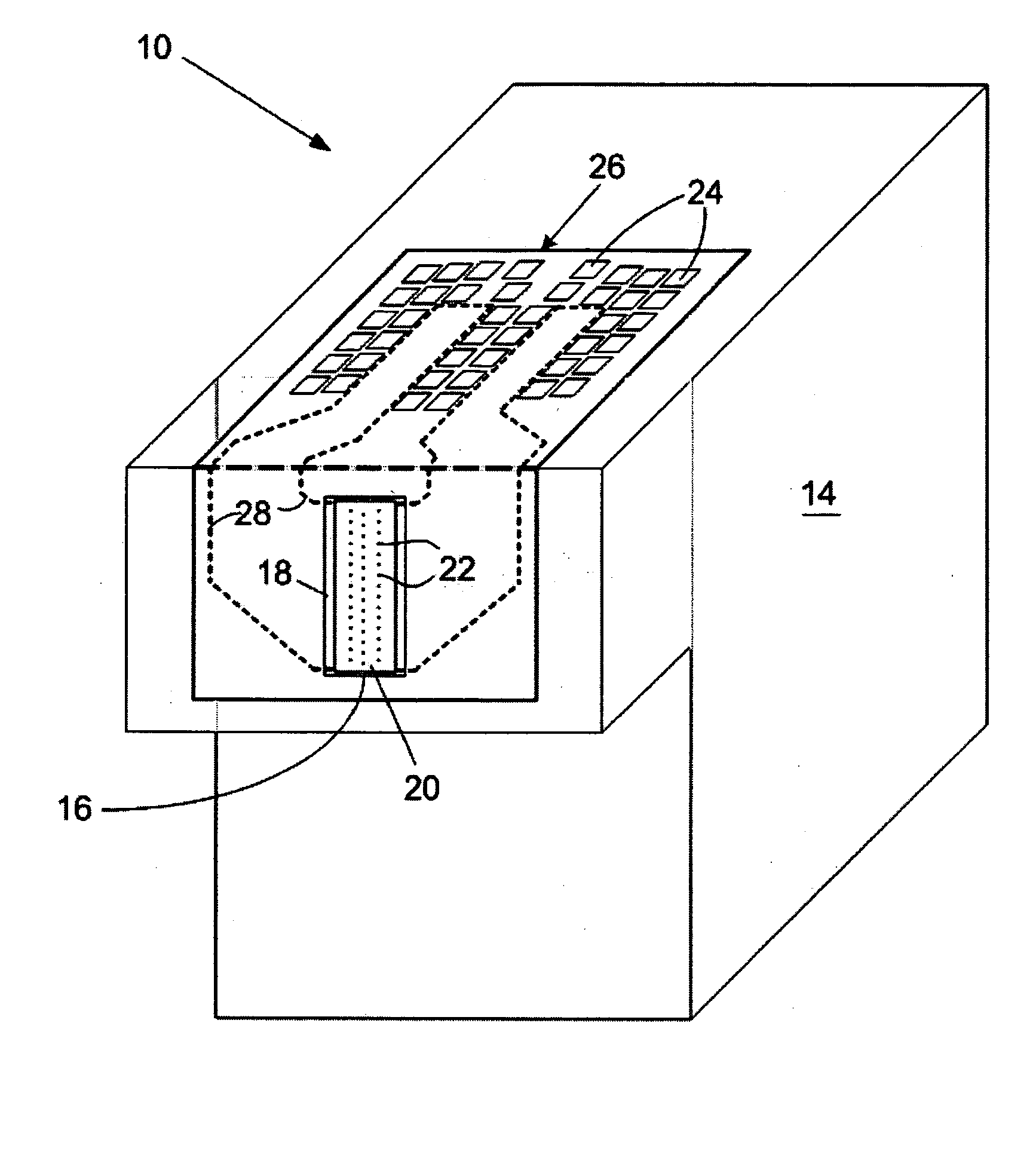
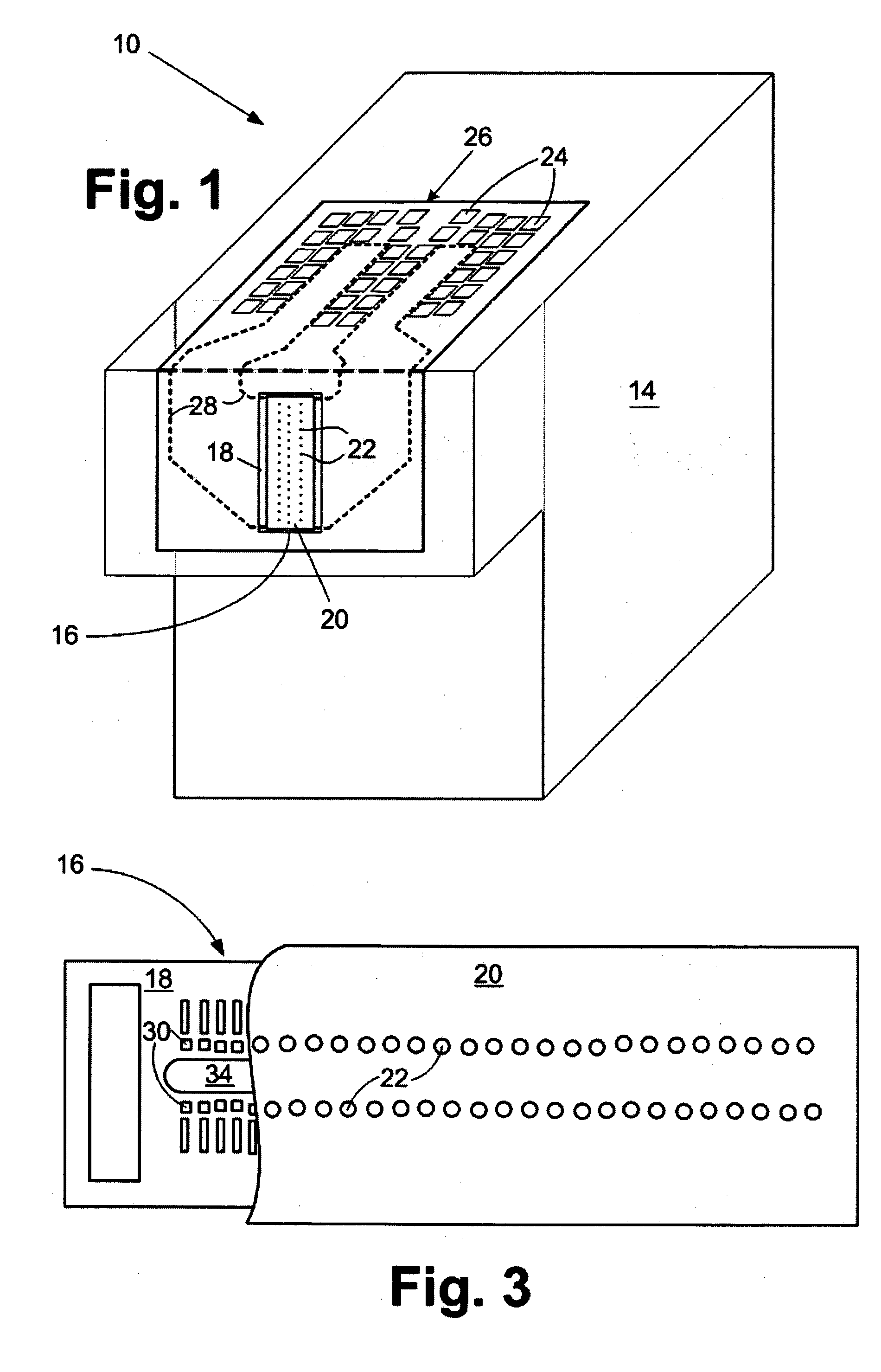
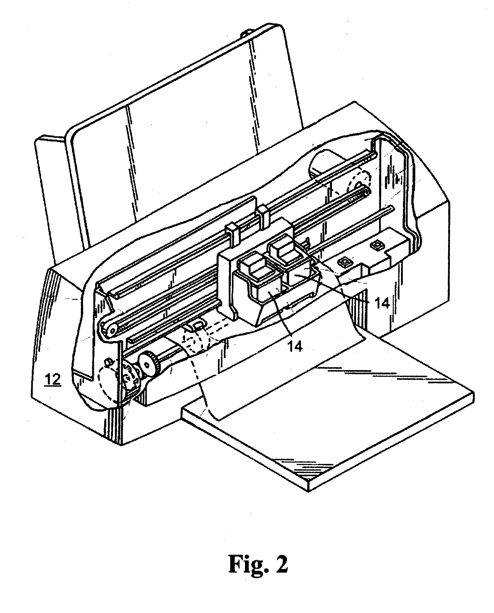
[0018] With reference to FIGS. 1-3, an ink jet printer cartridge 10 containing a printhead 16 for an ink jet printer 12 is illustrated. The cartridge 10 includes a cartridge body 14 for supplying a fluid such as ink to the printhead 16. The fluid may be contained in a storage area in the cartridge body 14 or may be supplied from a remote source to the cartridge body 14.

[0019] The printhead 16 includes a semiconductor substrate 18 and a nozzle plate 20 containing nozzle holes 22 attached to the substrate 18, or in another embodiment, attached to a thick film layer on the substrate. It is preferred that the cartridge 10 be removably attached to the ink jet printer 12. Accordingly, electrical contacts 24 are provided on a flexible circuit 26 for electrical connection to the ink jet printer 12. The flexible circuit 26 includes electrical traces 28 that are connected to the substrate 18 of the printhead 16.

[0020] An enlarged cross-sectional view, not to scale, of a portion of a printhe...


PUM


Abstract

A high resolution printhead for an ink jet printer. The printhead includes a semiconductor substrate containing at least one ink feed edge and a plurality of ink ejection actuators spaced a distance from the ink feed edge. Each of the ink ejection actuators has an aspect ratio ranging from about 1.5:1 to about 6:1. A nozzle plate is attached to the semiconductor substrate. The nozzle plate contains a plurality of nozzle holes, ink chambers and ink channels laser ablated in the nozzle plate corresponding to the plurality of ink ejection actuators. Adjacent nozzle holes are spaced apart with a pitch ranging from about 600 to about 1200 dpi. The distance from the ink feed edge is substantially the same for each of the ink ejection actuators.

Description

FIELD OF THE INVENTION [0001] The invention relates to ink jet printheads and in particular to ink jet printheads having increased resolution and methods for making the printheads. BACKGROUND OF THE INVENTION [0002] Ink jet printers continue to experience wide acceptance as economical replacements for laser printers. Such ink jet printers are typically more versatile than laser printers for some applications. As the capabilities of ink jet printers are increased to provide higher quality images at increased printing rates, printheads, which are the primary printing components of ink jet printers, continue to evolve and become more complex. [0003] Improved print quality requires that the printheads provide an increased number of ink droplets. In order to increase the number of ink droplets from a printhead, printheads are designed to include more nozzles and corresponding ink ejection actuators. The number of nozzles and actuators for a “top shooter” or “roof shooter” printhead can b...

Claims


Application Information

Patent Timeline
Patent Type & Authority Applications(United States)
IPC IPC(8): B41J2/14
CPCB41J2/1404B41J2202/11B41J2002/14387
Inventor MAHER, COLIN G.POWERS, JAMES H.
Owner SLINGSHOT PRINTING LLC
Learn More