
Electronic endoscope apparatus capable of converting images into HDTV system

a technology of endoscope and hdtv system, which is applied in the field of configuration, can solve the problems of reducing the quality of the image, reducing the resolution of the ccd indicating high-quality image, and generating an expensive apparatus, and achieves the effect of higher-quality images

Inactive Publication Date: 2005-08-11
FUJI PHOTO OPTICAL CO LTD
View PDF5 Cites 47 Cited by
  • Summary
  • Abstract
  • Description
  • Claims
  • Application Information

AI Technical Summary

Benefits of technology

[0011] The present invention has been developed to solve the above-mentioned problem, and aims at providing an electronic endoscope apparatus which uses image output by digital processing for supply to a personal computer, etc., obtains an image in a high vision television system in a simple configuration at a low cost without reducing the resolution although an electronic endoscope loaded with solid-state image pickup elements having different numbers of pixels is connected, and can display an image in an easy observation state.
[0014] According to the high vision system converter of the electronic endoscope apparatus of the above-mentioned first invention, although an electronic endoscope having a different number of pixels (resolution) for the CCD is connected using the output of the differential signal output unit for supply of a digital image to a personal computer, etc., an image by a high vision television system can be generated in a simple configuration and at a low cost without lowering the resolution of the CCD, an image of an observation object can be displayed and observed on a high vision monitor with the same size by the number of pixels, or recorded. Therefore, in a routine check, etc. in which a number of endoscopic images (moving pictures or still images) are observed, there is an effect of a quick and easy observation and diagnosis. Furthermore, by using the high vision system converter as an adapter device which satisfies the standards of EMC and electric safety required in a medical field, the observation of a high vision image in a medical field can be easily realized.

Problems solved by technology

However, if an NTSC signal is converted to a high vision television signal as described above, there is the restriction by the resolution of the NTSC video signal, and the resolution of the CCD indicating high-quality image cannot be fully utilized.
Furthermore, the CCD for different numbers of pixels is loaded for the electronic endoscope, and if the difference in the number of pixels of the CCD and a change for a large number of pixels are supported by the arrangement or update (exchange) of a conversion circuit for a high vision television signal in a processor device, then the entire system is costly and generates an expensive apparatus.
Additionally, equipment for use in a medical field is requested to meet strict standards on the EMC (electromagnetic compatibility) and electric safety, and it is not practical to satisfy the medical standards in a dedicated large device such as a personal computer, etc. for conversion to a high vision television signal.

Method used


Image

  • Electronic endoscope apparatus capable of converting images into HDTV system
  • Electronic endoscope apparatus capable of converting images into HDTV system
  • Electronic endoscope apparatus capable of converting images into HDTV system

Examples


first embodiment

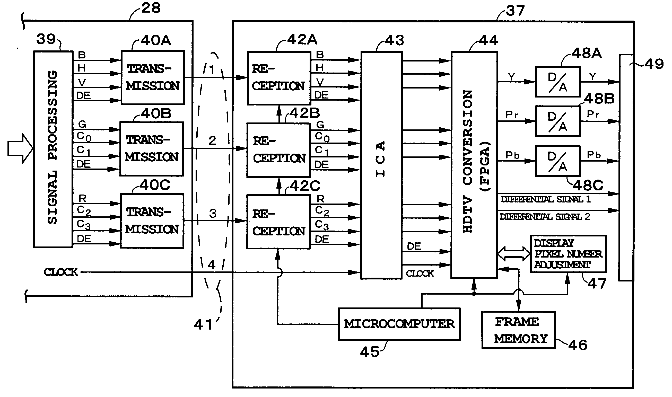
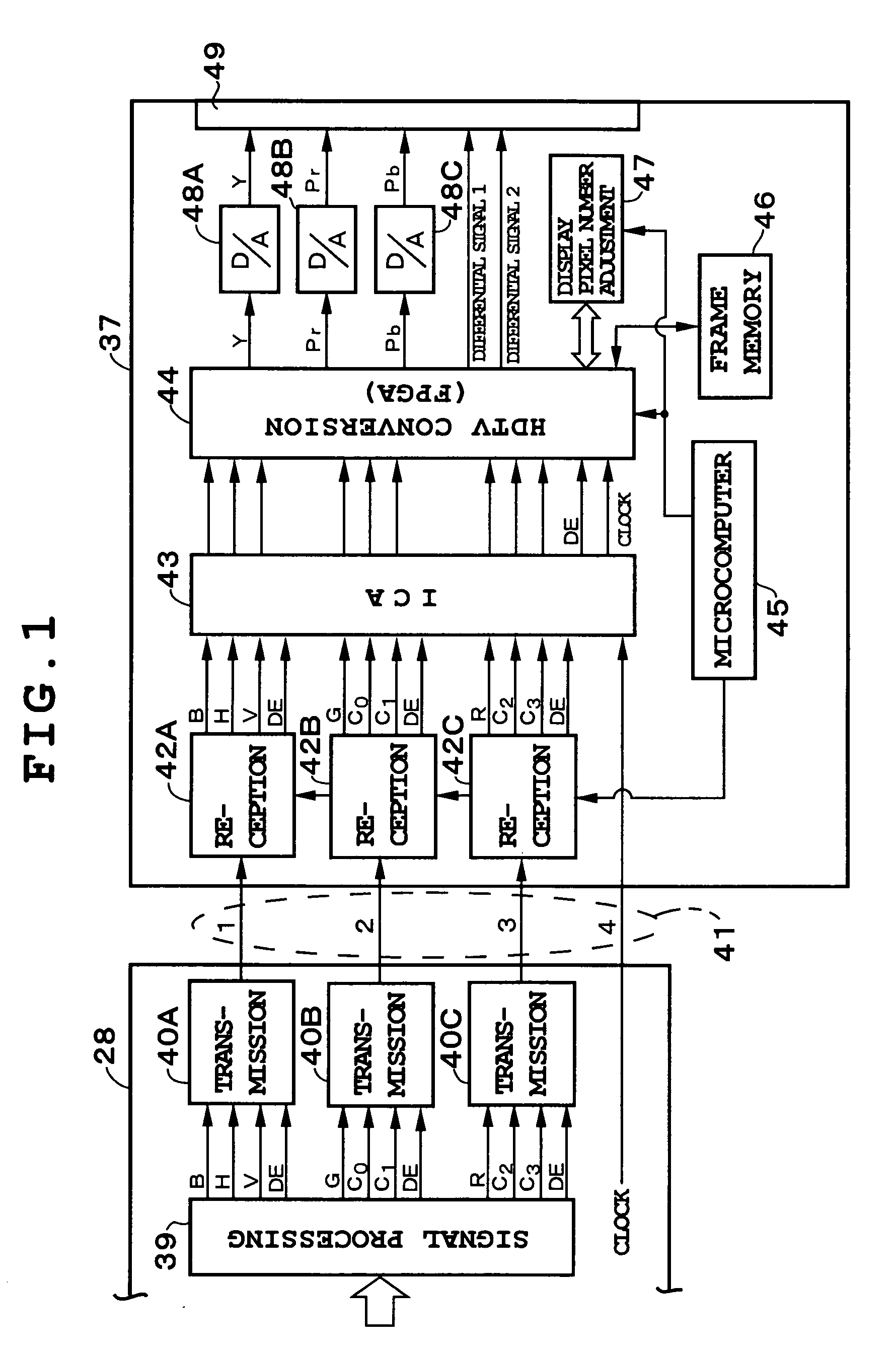
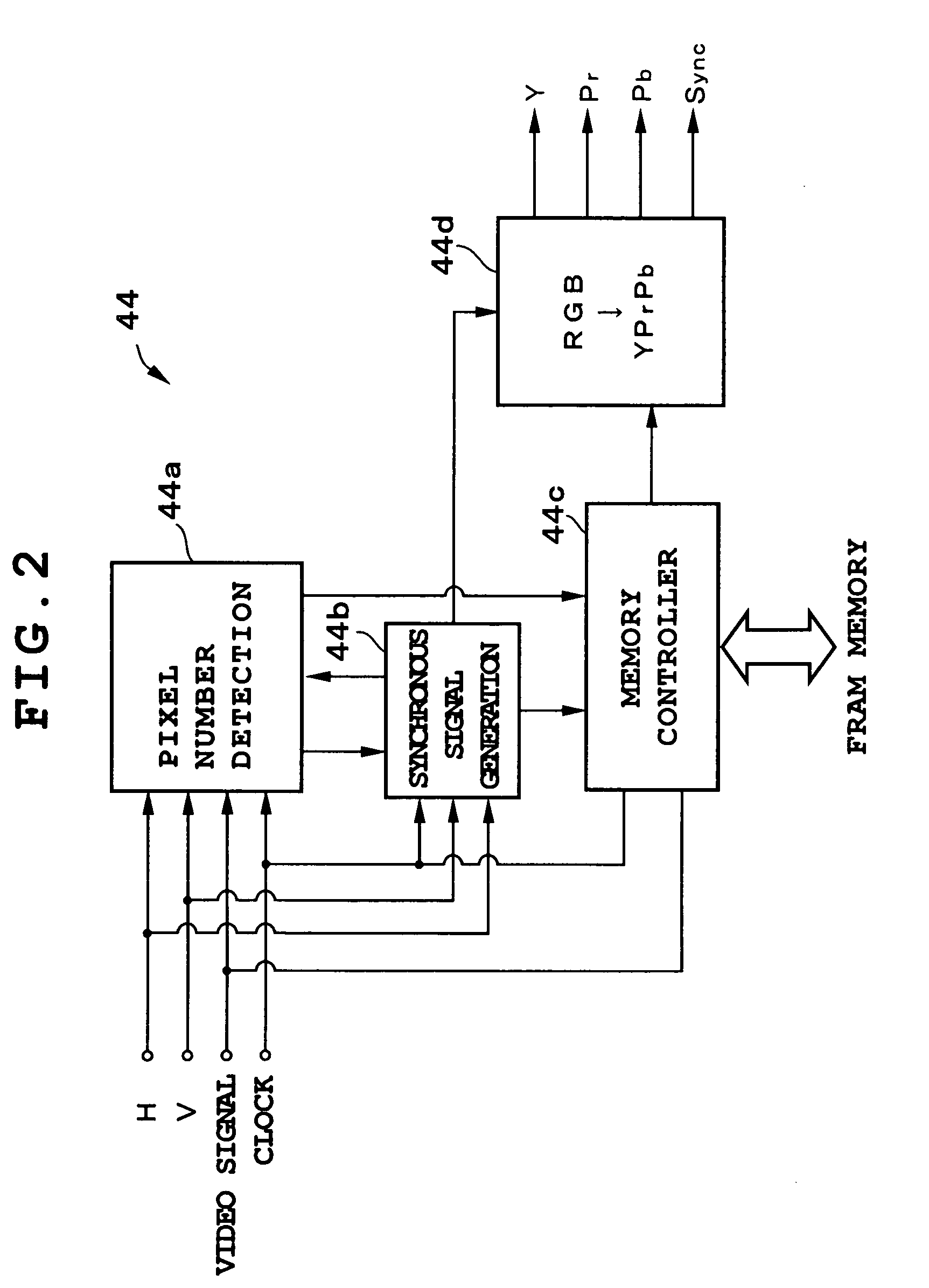
[0026] FIGS. 1 to 3 show the configurations of the electronic endoscope apparatus according to the first embodiment of the present invention. The entire configuration of the apparatus is first described below. In FIG. 3, an electronic endoscope (electronic scope) 10 is provided with CCDs 11 which are solid-state image pickup elements at the tip portion. The CCDs 11 can be various types for 400 thousand pixels, 80 thousand pixels, 1.31 million pixels, etc. A duplex correlation sampling (CDS) circuit 12 for sampling a capture signal output from the CCD 11, memory (EEPROM) 13 for storing the identification information, about the electronic endoscope 10, video processing information, etc. are also provided. The light of the light source device not shown in the attached drawings is supplied to the electronic endoscope 10 through a light guide, and an image of an observation object is captured by the CCD 11 by the illumination from the tip portion. Various electronic endoscopes 10 loaded ...

second embodiment

[0040] The second embodiment is a display pixel number adjustment circuit 50 for performing an electronic scaling process in the processor device 16 as shown in FIG. 3. The display pixel number adjustment circuit 50 has, for example, image memory, and connected to the third DSP 21. That is, in the display pixel number adjustment circuit 50, the video signal generated by the third DSP 21 is temporarily stored in the image memory, and the video signal read from the image memory is expanded to a predetermined number of pixels, that is, the number of pixels according to, for example, the SXGA in the electronic scaling process, and is output to the fourth DSP 27.

[0041] As in the first embodiment, the image of 1280×960 pixels is not electronically expanded, but an image in accordance with the XGA standard is expanded from 1024×768 pixels to 1280×960 pixels as shown in FIG. 5A, and an image in accordance with the VGA standard is expanded from 640×480 pixels to 1280×960 pixels as shown in ...


PUM


Abstract

A processor device having electronic endoscopes having different number of pixels of CCDs is provided with a DVI circuit for generating a digital video signal of display standard of a personal computer, etc. and outputting it as a differential signal, and a high vision system converter is connected to and arbitrarily removed from the output side of the DVI circuit. In the high vision system converter, a video signal having different number of pixels is electronically scaled to a number of display pixels of, for example, an SXGA standard by detecting the number of pixels of the input digital video signal, and is displayed on a high vision screen. Thus, the resolution of the image of the CCD can be maintained.

Description

BACKGROUND OF THE INVENTION [0001] The application claims the priority of Japanese Patent Applications No. 2004-18897 filed on Jan. 27, 2004 which is incorporated herein by reference. [0002] 1. Field of the Invention [0003] The present invention relates to the configuration of an electronic endoscope apparatus, and more specifically to an electronic endoscope apparatus capable of outputting an image of an observation object to a monitor in a high vision television system in an environment in which various types of electronic endoscopes having different numbers of pixels of a solid-state image pickup element are used. [0004] 2. Description of the Related Art [0005] An electronic endoscope apparatus is loaded with a CCD (charge coupled device), etc. which is a solid-state image pickup element at the tip portion of an electronic endoscope (electronic scope). The CCD captures an image of an observation object using the illumination of the light from the light supply device. A capture si...

Claims


Application Information

Patent Timeline
Patent Type & Authority Applications(United States)
IPC IPC(8): A61B1/05A61B1/04H04N5/225H04N7/18
CPCA61B1/05
Inventor ABE, KAZUNORI
Owner FUJI PHOTO OPTICAL CO LTD
Learn More