
Apparatus and method for recording data in optical recording medium

a technology of optical recording medium and apparatus, applied in the field of optical recording, can solve the problems of deformation of recording marks into teardrops, inability to achieve subsequent phase change to the amorphous state satisfactorily, and degradation of recording quality, so as to improve the recording quality of phase-change optical recording media

Inactive Publication Date: 2005-08-11
RICOH KK
View PDF4 Cites 4 Cited by
  • Summary
  • Abstract
  • Description
  • Claims
  • Application Information

AI Technical Summary

Benefits of technology

[0014] Therefore, it is an object of the present invention to improve the recording quality of phase-change optical recording media under high-temperature environments.
[0020] With the method and the apparatus, the amplitude of short pulses defining a pulse sequence is controlled in response to the temperature change occurring near the phase-change optical recording medium. Consequently, the recording quality is improved even under a high-temperature environment, such as inside a personal computer. Since need for a heat releasing fin to be used in the optical recording and reproducing apparatus is eliminated, the optical recording and reproducing apparatus can be made compact and light. In addition, and the manufacturing cost can be reduced.

Problems solved by technology

It is pointed out in this publication that variation in wavelength is one of the factors that cause degradation of the recording quality.
However, with the single-pulse optical recording techniques, recording marks are likely to deform into tear-drops due to heat accumulation, and subsequent phase change to the amorphous state cannot be accomplished satisfactorily due to insufficient cooling rate.
Thus, recording marks with low reflectance with respect to laser light cannot be acquired when using the single-pulse recording scheme.
If the temperature surrounding the optical disk rises to be high, the recording layer is heated too much during the rapid heating process, while the cooling rate becomes insufficient in the rapid cooling process.
Consequently, the recording quality is degraded.
Due to the high-speed operations and multi-function configuration of recent personal computers, the amount of heat generated by various components is increasing inside the personal computer, and the environmental temperature of the personal computer inevitably rises.
If the recording strategies optimized for room temperature are applied to the high temperature environment, such as inside personal computers, the recording quality designed to be achievable at room temperature cannot be acquired.

Method used


Image

  • Apparatus and method for recording data in optical recording medium
  • Apparatus and method for recording data in optical recording medium
  • Apparatus and method for recording data in optical recording medium

Examples


Embodiment Construction

[0032] The preferred embodiment of the present invention is now explained below in conjunction with attached drawings.

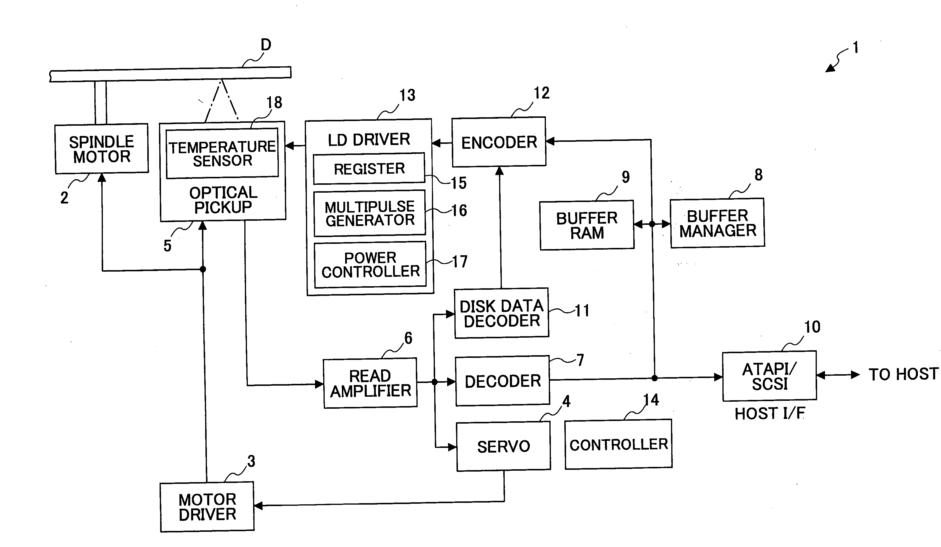
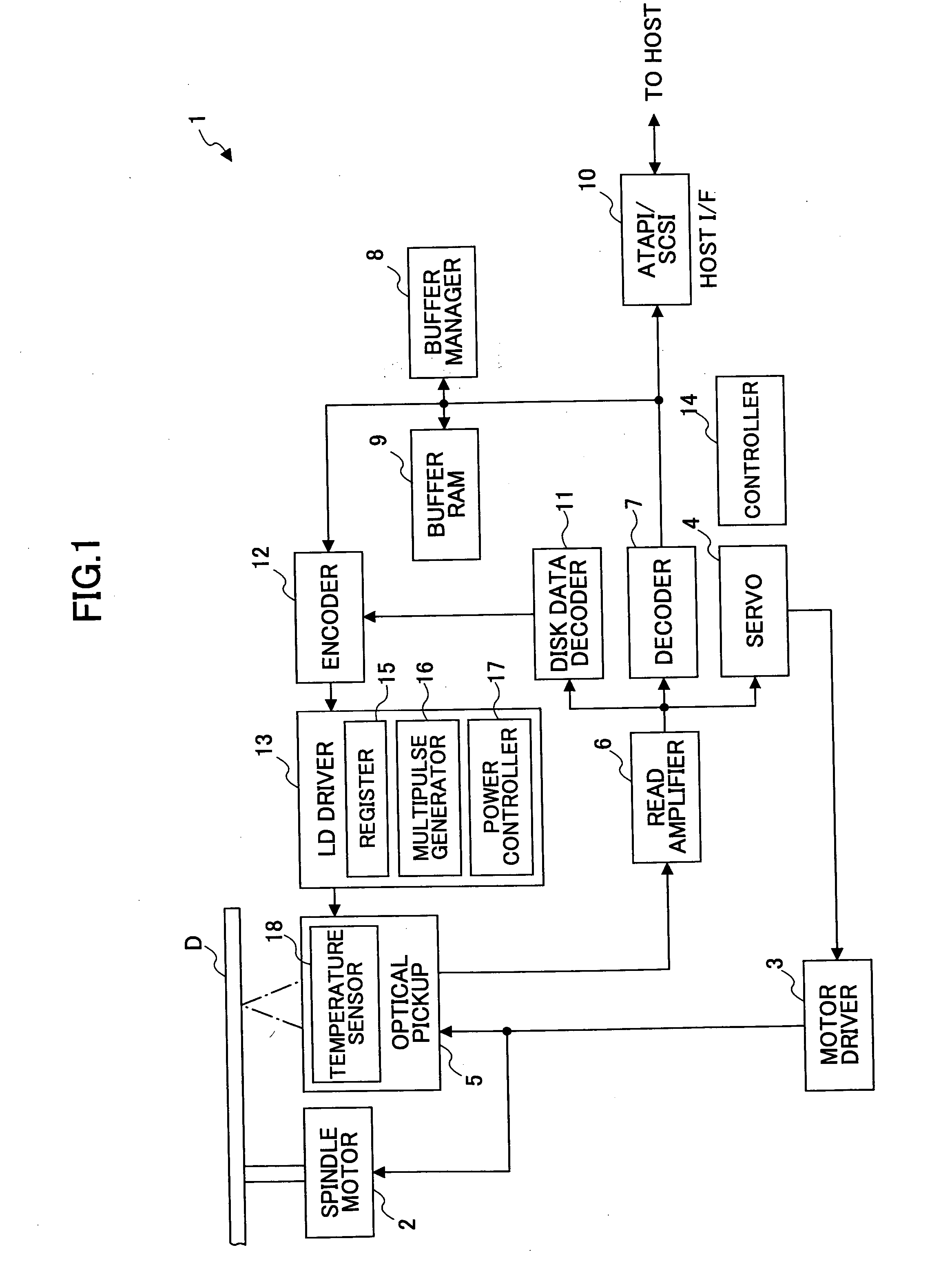
[0033]FIG. 1 is a block diagram illustrating the structure of an optical disk recording and reproducing apparatus 1 according to an embodiment of the invention. The optical disk recording and reproducing apparatus 1 includes a spindle motor 2 for rotating an optical disk D, servo means 4, an optical pickup 5, a read amplifier 6, a decoder 7, a buffer manager 8, a buffer RAM 9, a host interface 10, a disk data decoder 11, an encoder 12, an LD driver 13, and a controller 14. The LD driver 13 includes a register 15, a multipulse generator 16, and a power controller 17. The arrows connecting these components in FIG. 1 indicate data flow, and physical connection between the controller 14 and each clock is omitted for the purpose of simplification.

[0034] Although not shown in FIG. 1, the optical pickup 5 includes a laser diode (LD) functioning as the light source, an opt...


PUM


Abstract

An optical data recording method for recording data in a phase-change optical recording medium using a sequence of one or more short pulses is provided. In this method, a temperature is detected at a prescribed spot around the optical recording medium. The amplitude of the short pulses is controlled in response to the detected temperature. Then, data are recorded in the optical recording medium using the sequence of amplitude-controlled short pulses.

Description

BACKGROUND OF THE INVENTION [0001] 1. Field of the Invention [0002] The present invention generally relates to optical recording for writing data in a phase-change optical recording medium using a sequence of recording pulses, and more particularly, to a pulse control technique for controlling the amplitude of the recording pulses when writing data in an optical disk. [0003] 2. Description of Related Art [0004] JP 2002-216349A discloses a technique for selecting the optimum waveform of a laser pulse in response to change in the surrounding temperature, when recording data in an organic dye recording layer of an optical disk (such as DVD-R). It is pointed out in this publication that variation in wavelength is one of the factors that cause degradation of the recording quality. Variation in wavelength is detected indirectly by measuring the temperature surrounding the laser, and the optimum shape of the recording pulse is selected based on the measurement result. [0005] In recent year...

Claims


Application Information

Patent Timeline
IPC IPC(8): G11B7/0045G11B7/0055G11B7/125G11B7/126
CPCG11B7/126G11B7/00557
Inventor NAGAMURA, ARITSUNE
Owner RICOH KK
Learn More