[0010] In the light of that stated above, the object of the present invention is to provide a plastic cap, which is considerably easier to manufacture and to open than prior-art solutions. Another object of the invention is to provide an easy and efficient way of making this cap. SUMMARY OF THE INVENTION
[0012] By joining the liner directly to the cap in connection with the injection-moulding, instead of placing the liner in the finished cap after injection-moulding, a much simpler and cheaper solution is obtained than in GB-A-1,571,938. Furthermore, this solution presents the
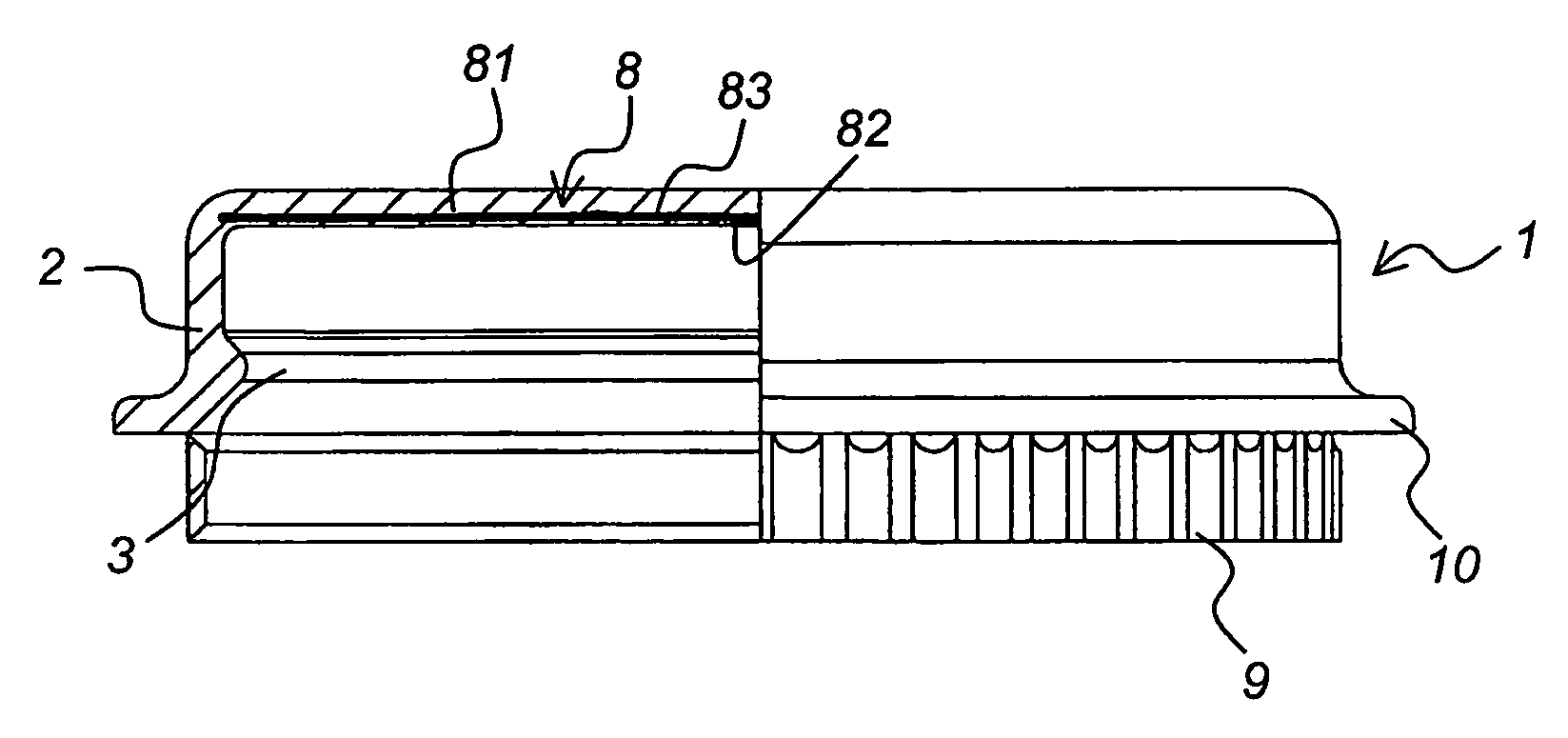
advantage that the liner cannot fall out of the cap, since it is already permanently joined to the plastic material of the cap in the injection-moulding. Moreover, the
radial projection serving as a
thumb grip is a more user-friendly solution than the pull tab according to the British patent specification, since the pull tab is intended for a
thumb-
index finger grip, which requires strong fingers and the use of both hands, one hand for holding the container and the other for the thumb-
index finger grip. As for the thumb grip used for the cap according to the invention, it can be obtained with one hand only, by the user's hand surrounding the container and the thumb making an opening motion towards the
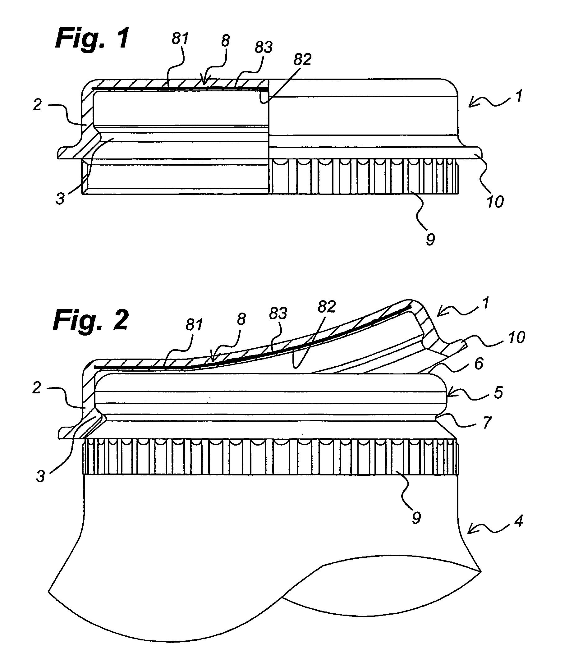
radial projection in the axial direction of the container. This axially directed opening motion can, of course, also be obtained in some other suitable manner, for example, by the radial projection being applied to the edge of a table and the container being moved downwards relative to this edge, and this motion is even easier to carry out as the cap, when opening the container, is bent away from the opening end surface of the container so that the temporary,
hermetic seal between the second plastic layer of the liner and the opening end surface of the spout is gradually broken. This feature is not stated in any one of the patent specifications mentioned above, in particular not in connection with the cap according to GB-A-1,571,938, in which radial reinforcing flanges are arranged to prevent bending.
[0016] According to an alternative embodiment, the second plastic layer of the liner is a layer which is applicable to the opening end surface of the container by
adhesive. The
advantage of this solution is that the cap according to the invention will be capable of sealing in an oxygen-tight manner also containers that are not suitable for induction or
ultrasonic welding.
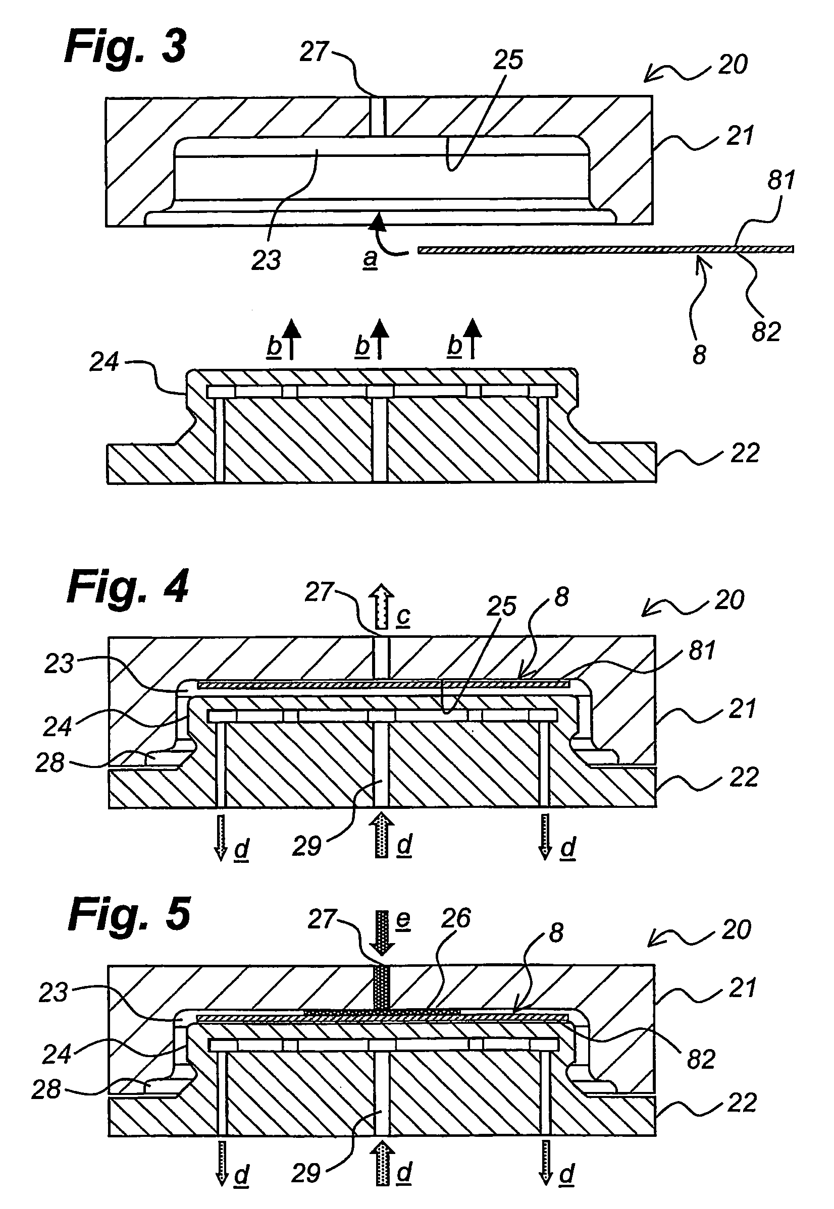
[0019] This method is considerably easier to carry out than the prior-art methods mentioned above, and owing to the application of the first flat side of the liner to a mould wall of the first mould part all previous limitations due to possible heating of the core of the mould are efficiently obviated. The application of the liner to the mould wall is preferably obtained by a negative pressure being created in said at least one opening in said mould wall.

