Affinity sensor for detecting specific molecular binding events and use thereof

a technology of molecular binding events and affinity sensors, applied in the field ofaffinity sensors, can solve the problems of inability to detect, low sensitivity and spatial resolution of signals emitted by individual marker molecules, and the limitations of the current automation of image analysis on the basis of chip technology, and achieve the effect of low expenditur

Inactive Publication Date: 2005-08-11
GENETRIX SL
View PDF3 Cites 5 Cited by
  • Summary
  • Abstract
  • Description
  • Claims
  • Application Information

AI Technical Summary

Benefits of technology

[0029] It is an object of the present invention to provide an affinity sensor for detecting specific molecular binding events, which in a rapid, sensitive, specific way detects the presence of molecules in routine operation at low expenditures, in particular the presence of bioactive molecules, as well as to provide for special applications of such an affinity sensor.

Problems solved by technology

The problem of the various optical methods is, that the sensitivity and the spatial resolution of the signals emitted by the individual markermolecules is too low for many applications, that the binding between two links of a specific molecular binding pair cannot be detected, and that the signals are very often superimposed by an unspecific background.
The technical limits of the current automation of the image analyzing on the basis of chip technology lies in a read-out of various microarray spots.
The disadvantage of this method lies in the fact that only one single electronic event occurs for one biomolecular binding event, whereby the variation of the redox state, which is effected, lasts only for a short time, so that the detection of each individual binding event had to take place flash-like.
This is not possible.
A substantial disadvantage of this conventional biosensor technology is the inherent low sensitivity of the measurements attained across the measuring electrodes that cannot be eliminated in that the ligands in an infinitely great density are bound to the measuring electrode, for example, by use of a dextran layer.
Due to the additional deposition of, as for example, a dextran layer and due to the spatial arrangement of the ligands, the concentration of ligands on the electrodes is indeed raised up to the sixfold compared to a ligand single layer, but a detection of rare binding events or even of a binding between two elements of a special molecular binding pair is not possible.
The disadvantage of these methods is that rare binding events cannot be detected by these technologies.
The detection of the differences in frequencies, however, requires equipment which still is very expensive and which, moreover, still is far from being utilized as a matter of routine.
This expensive method has the disadvantage that it limits its application to the detection of single-stranded nucleic acids fragments of a defined length and that it is not suited for further biomolecules.

Method used


Image

  • Affinity sensor for detecting specific molecular binding events and use thereof
  • Affinity sensor for detecting specific molecular binding events and use thereof
  • Affinity sensor for detecting specific molecular binding events and use thereof

Examples


Embodiment Construction

[0031] The invention will be explained hereinafter in more detail by virtue of schematical embodiments under reference to the drawings. There is shown in:

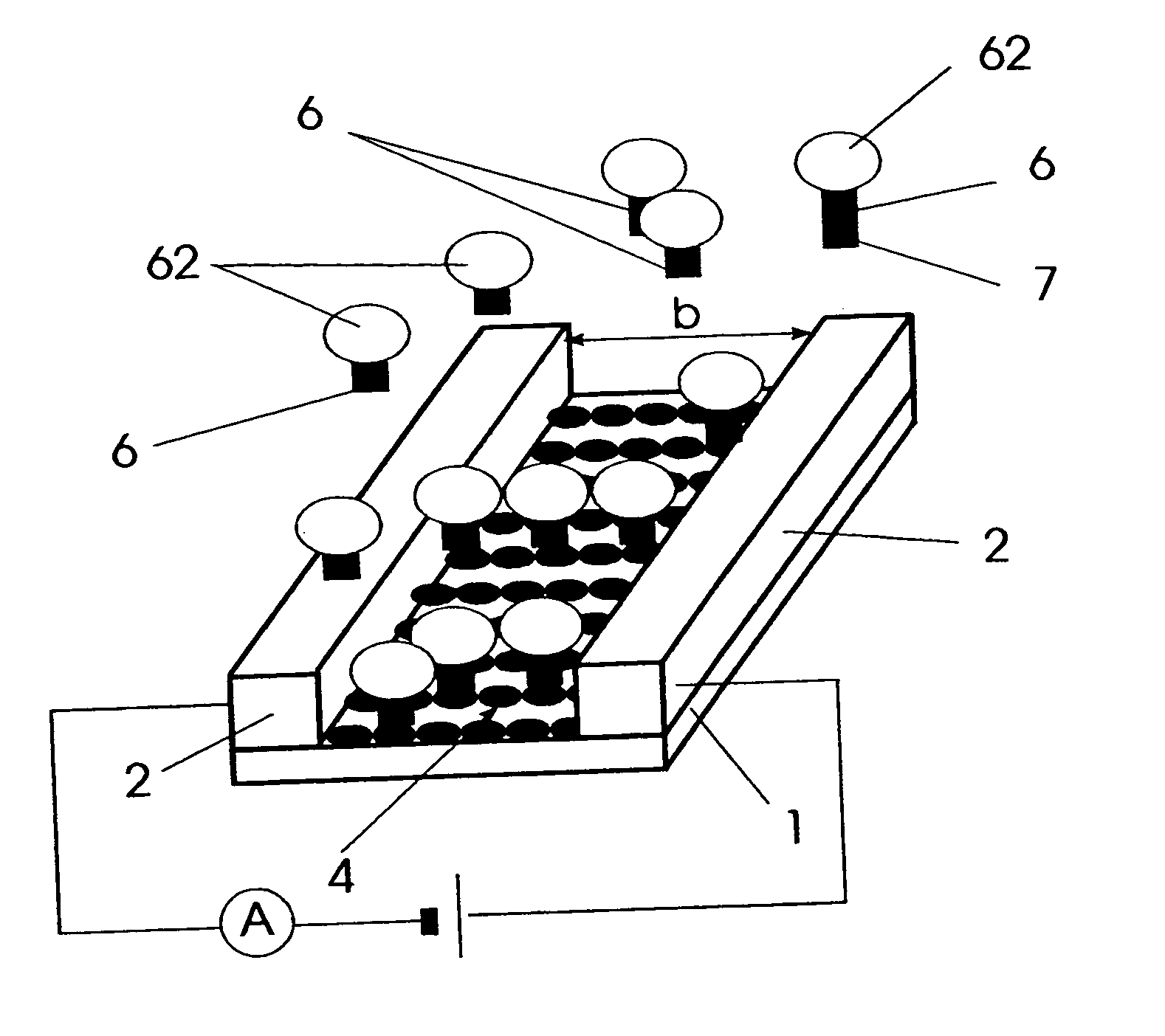
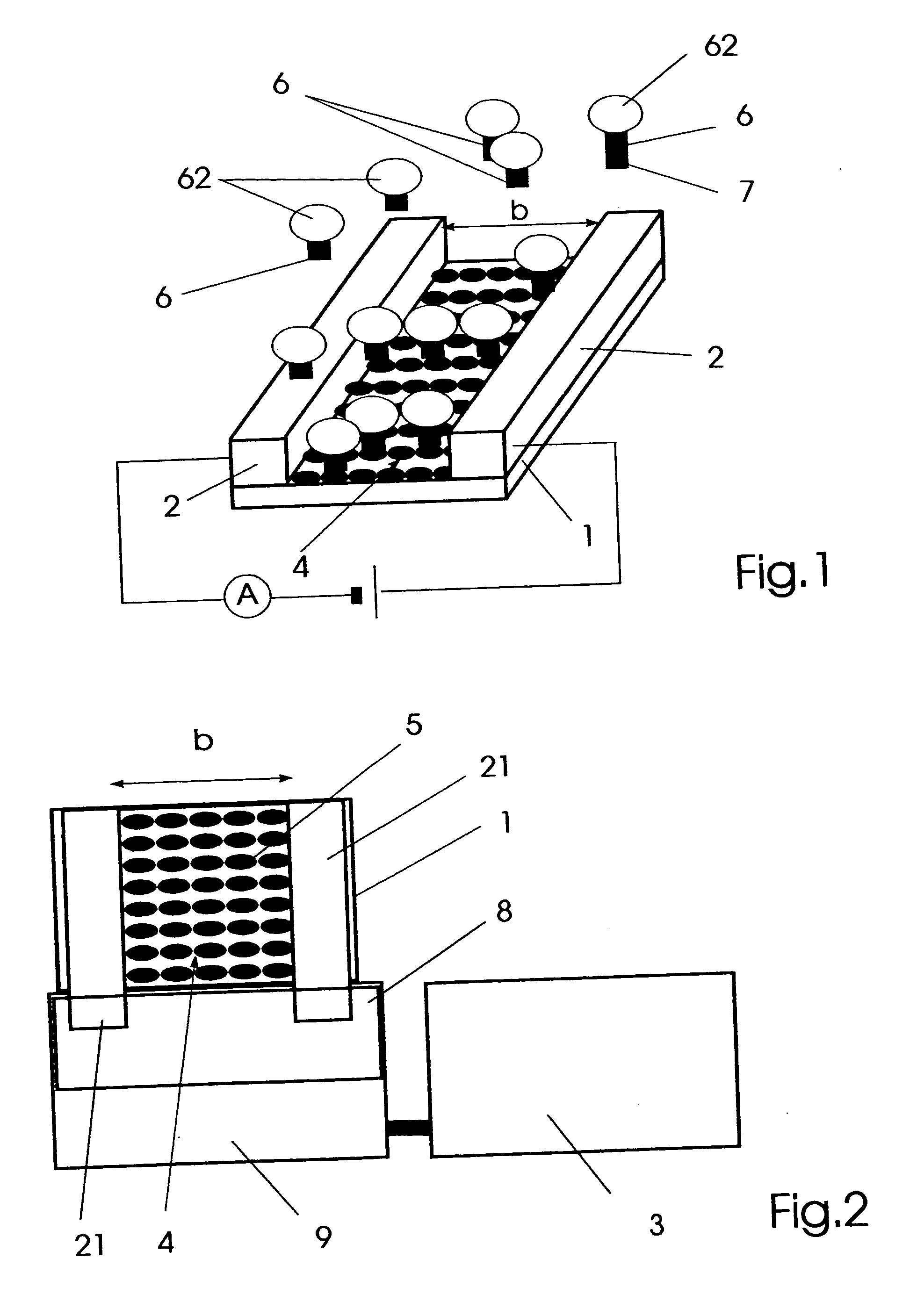
[0032]FIG. 1 an affinity sensor for detecting specific molecular binding events,

[0033]FIG. 2 a schematical representation of the affinity sensor for detecting specific molecular binding events,

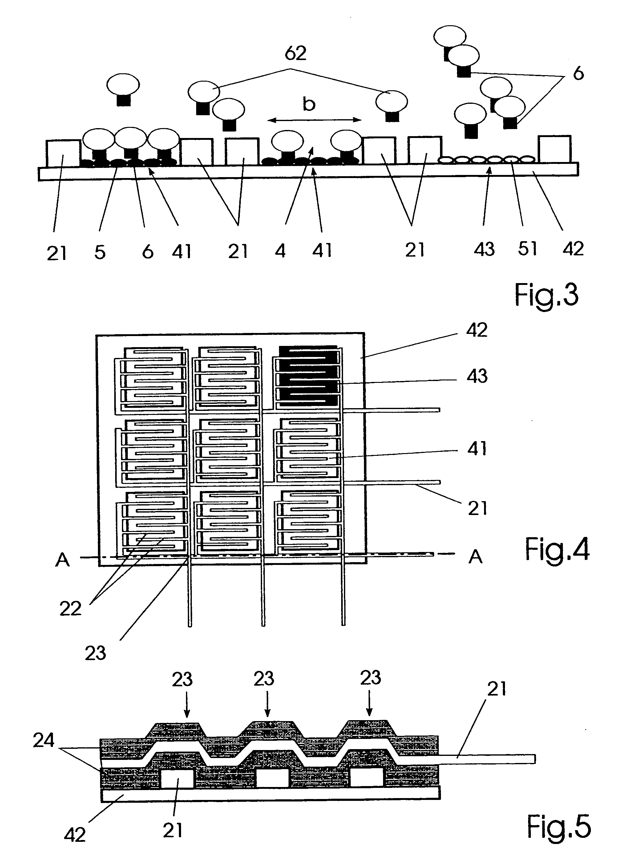
[0034]FIG. 3 a cross-sectional view of an embodiment of the affinity sensor for detecting specific molecular binding events,

[0035]FIG. 4 a plan view of an embodiment of the affinity sensor in the form of an affinity chip, and

[0036]FIG. 5 a sectional view along the plane A-A of the affinity chip represented in FIG. 4.

DETAILED DESCRIPTION

[0037] An affinity sensor for detecting specific molecular binding events shown in FIGS. 1 and 2, is comprised of a carrier substrate 1 which is provided with electrodes 2 enclosing an area 4 that is provided with immobilized specific binding partners 5. Thereby the area 4 represents a discontinuity in an...


PUM

PropertyMeasurementUnit
heightaaaaaaaaaa
sizeaaaaaaaaaa
lengthaaaaaaaaaa

Abstract

The invention relates to an affinity sensor for detecting specific molecular binding events, for use in the field of molecular biology, e.g., in medical diagnostics, especially in biosensor technology or in DNA microarreay tests. The aim of the invention is to provide an affinity sensor of this type for rapidity, sensitively, specifically, economically and routinely detecting the presence of molecules, especially bioactive molecules, and to provide special applications for an affinity sensor of this type. To this end, the affinity sensor consists of a support substrate which is provided with at least two electrodes. The electrodes are situated equidistantly from each other and cover an area on both sides, at least this area being provided for receiving immobilised specific binding partners which are capable of coupling complementary corresponding binding partners directly or with other specific binding molecules. The area is established with a minimum width b, in such a way that at least one complementary corresponding binding partner which is provided with an electroconductive particle can be received in the area in such a way as to guarantee the possibility of a tunnel-type contact junction forming between the particle and the electrodes in each case. The affinity sensor is used for biomonitoring.

Description

REFERENCE TO RELATED APPLICATION [0001] This is a divisional application and hereby incorporates by reference the entire disclosure of application Ser. No. 09 / 869,206, filed Jun. 25, 2001.BACKGROUND OF THE INVENTION [0002] The invention relates to an affinity sensor for detecting specific molecular binding events, as is particularly used in the molecularbiological field, for example, in medical diagnostics, in biosensor technology or in DNA-microarray technology, and application of the same. [0003] Biosensors are solid phase measuring devices that are comprised of at least one biological receptor, a transducer and a subsequently connected electronic unit. [0004] The receptor utilizes biologically active reagents such as, for example, is antibodies for detecting a specific substance such as, for example, antigens. The transduction of detection events into detectable signals is performed by the transducer, for example, by electrochemical, optical, piezoelectric, or calorimetric method...

Claims


Application Information

Patent Timeline
Patent Type & Authority Applications(United States)
IPC IPC(8): C12M1/00C12M1/34C12Q1/04C12Q1/68G01N1/28G01N27/02G01N27/04G01N33/483G01N33/543G01N33/566G01N37/00
CPCG01N33/5438B01J2219/00653
Inventor FRITZSCHE, WOLFGANGCZAKI, ANDREAKOEHLER, JOHANN MICHAELWIEGAND, ANTJEOOSTING, LOUISSCHUT, FREDERIKTJWAN TAN, PARIS SOM
Owner GENETRIX SL
Why Eureka
Try Eureka