System, method, and apparatus for non-traditional kinematics/tooling for efficient charging of lapping plates

Inactive Publication Date: 2005-08-11
HITACHI GLOBAL STORAGE TECH NETHERLANDS BV
View PDF7 Cites 9 Cited by
  • Summary
  • Abstract
  • Description
  • Claims
  • Application Information

AI Technical Summary

Benefits of technology

[0014] One embodiment of a system, method, and apparatus for diamond charging of lapping plates incorporates the use of individual ceramic inserts that are mounted into a stainless steel frame to form a novel charging tool. The charging tool is rotated clockwise, rather than counterclockwise, against the counterclockwise rotating tin plate. This configuration performs a much faster diamond impregnation into the plate without scraping off the diamond slurry from the plate. This design uses the diamond material in the plate charging slurry more efficiently than prior art methods.
[0015] The inserts may be formed from high density ceramic in a round or cylindrical pad-like design. This design allows for higher pressure contact between the inserts and the tin plate than conventional methods. As a result, the amount of time required to charge a plate is greatly reduced and only a small fraction of the diamond slurry is wasted, thereby producing a higher yield than prior art systems.

Problems solved by technology

Current traditional methods used industry wide for diamond charging of lapping plates are very inefficient.
Long cycle times and large amounts of wasted diamond material make these diamond charging processes very expensive.
For example, the diamond material can cost millions of dollars each year.
Unfortunately, because of the inefficiencies of current systems, approximately 90% of the diamond material is lost and unrecoverable in the process.
The drawbacks of this process are that the centrifugal forces involved and the scraping action of the ceramic ring allow for most of the diamond slurry to be removed from the plate surface before it has a chance to deliver diamond to the lap plate surface.

Method used


Image

  • System, method, and apparatus for non-traditional kinematics/tooling for efficient charging of lapping plates
  • System, method, and apparatus for non-traditional kinematics/tooling for efficient charging of lapping plates
  • System, method, and apparatus for non-traditional kinematics/tooling for efficient charging of lapping plates

Examples


Embodiment Construction

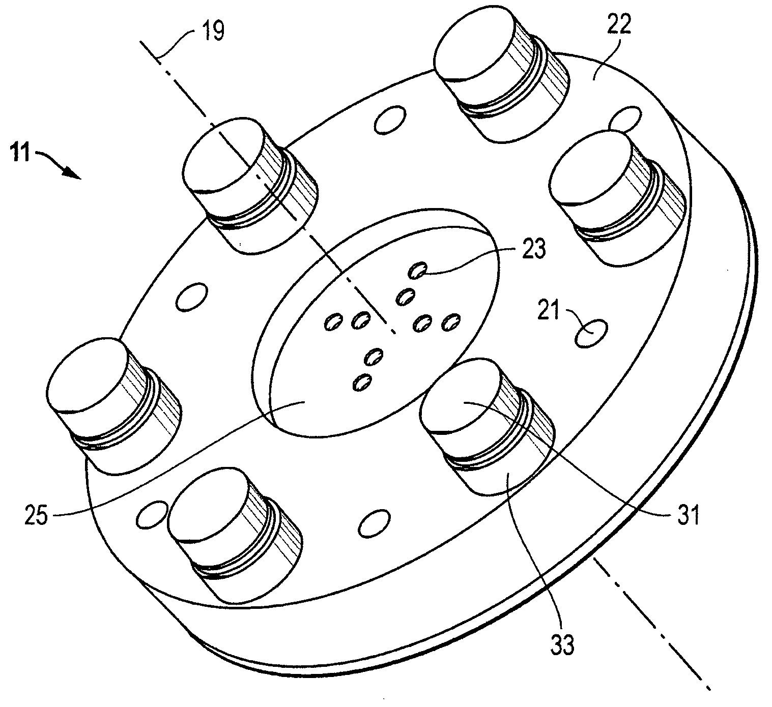
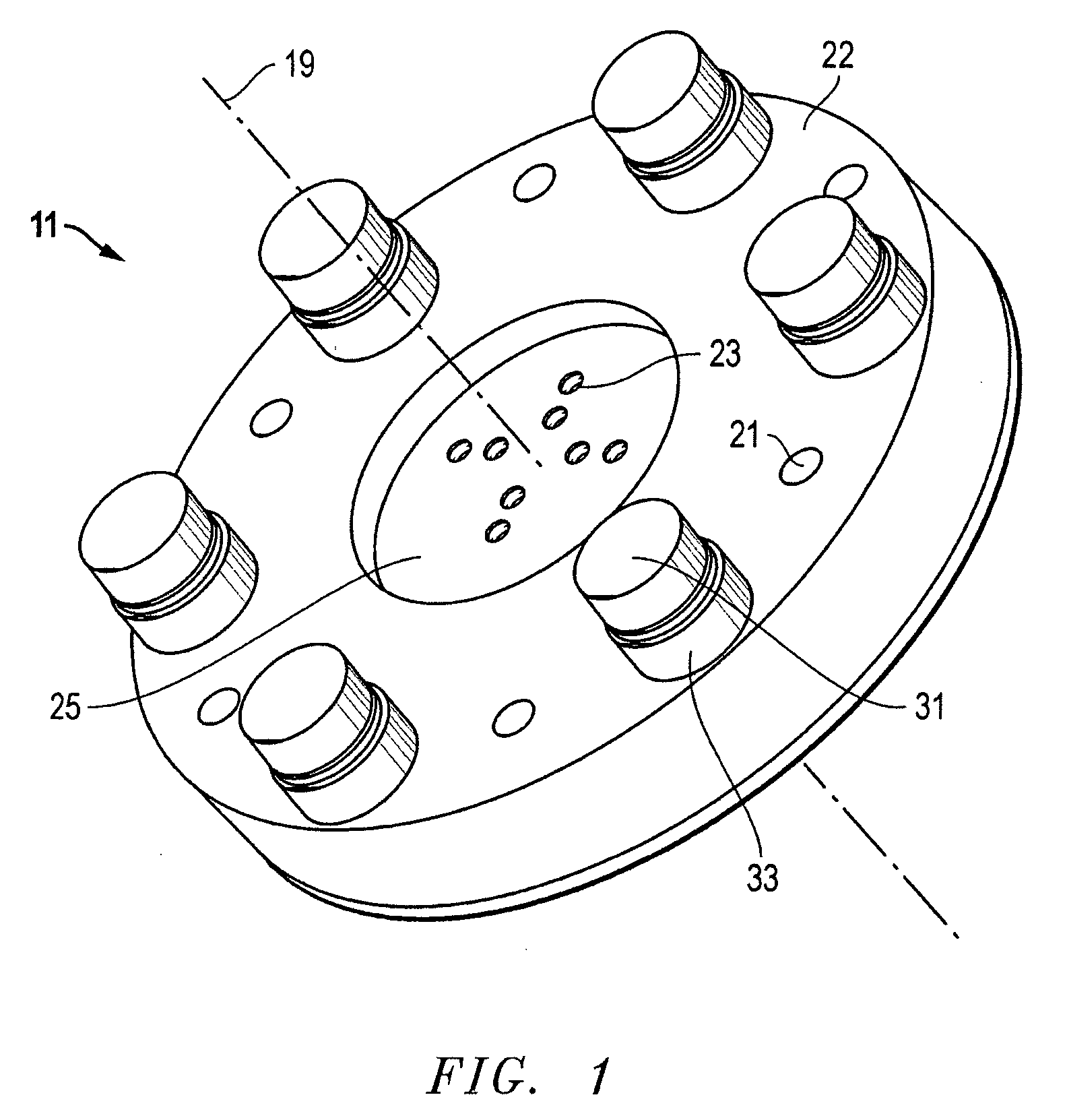
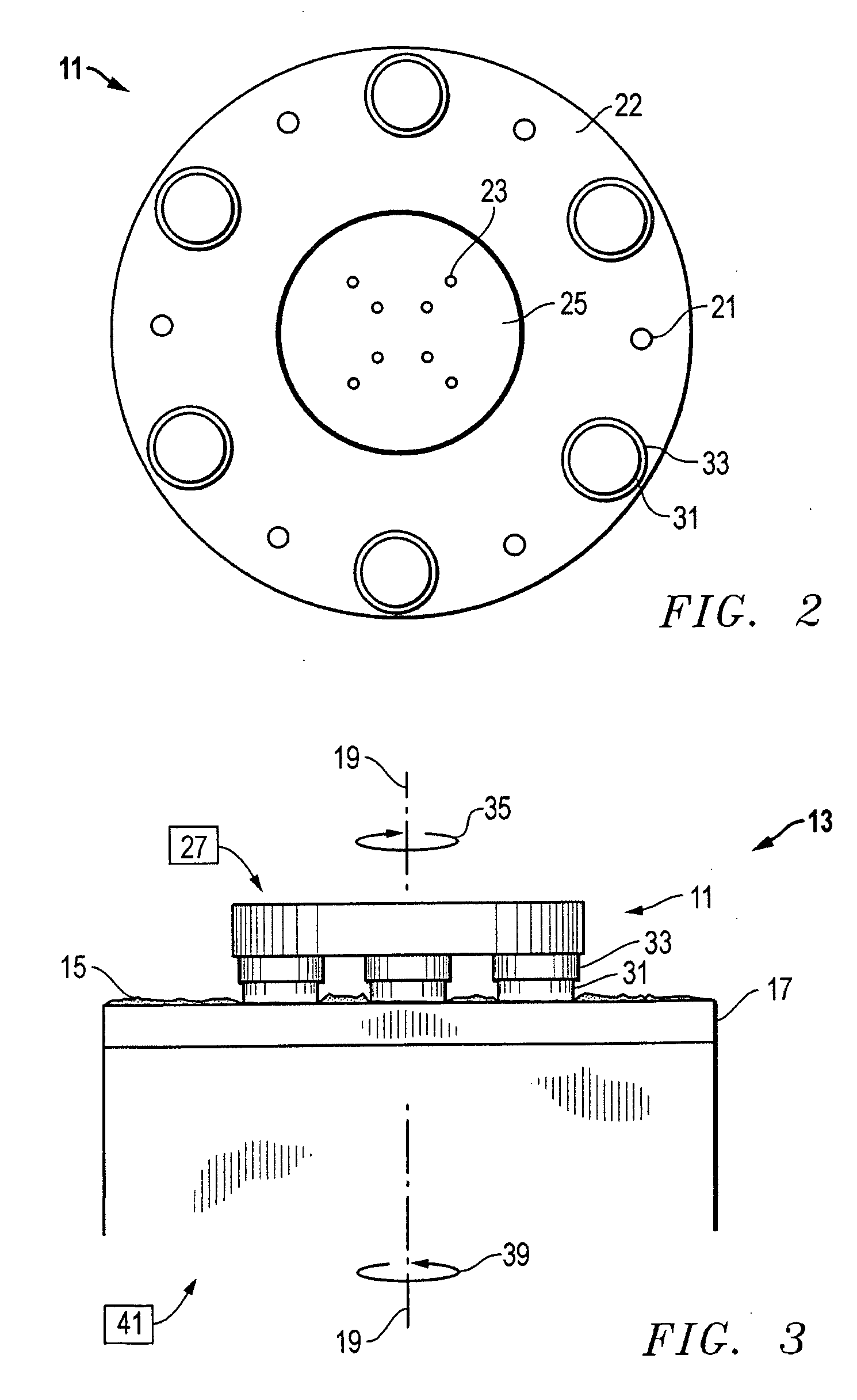
[0021] Referring to FIGS. 1 and 2, one embodiment of a fixture 11 for charging a lapping plate is shown. The fixture 11 comprises a portion of a charging tool 13 (FIG. 3) that uses an abrasive (e.g., diamond) when a slurry 15 containing the abrasive is introduced between the charging tool 13 and the lapping plate 17. In the embodiment shown, the fixture 11 has a circular, plate-like shape, a rotational axis 19, and is preferably formed from stainless steel. The fixture 11 also has a plurality of apertures 21 (six shown) in its lower surface 22, and a set of mounting holes 23 located in a recess 25 for engaging drive means 27 for rotating the fixture 11 about rotational axis 19. Both apertures 21 and mounting holes 23 are axially symmetric, and the recess 25 comprises a centrally located, cylindrical depression in the embodiment of FIGS. 1 and 2.

[0022] Fixture 11 also comprises a plurality (six shown) of discrete, discontinuous charging elements 31 that are removably mounted thereto...


PUM

PropertyMeasurementUnit
Pressureaaaaaaaaaa
Volumetric flow rateaaaaaaaaaa
Pressureaaaaaaaaaa

Abstract

A system for charging lapping plates incorporates the use of individual ceramic inserts that are mounted into a stainless steel frame to form a novel charging tool. The charging tool is rotated clockwise against a counterclockwise rotating tin plate. This configuration performs a rapid diamond impregnation into the plate without scraping off the diamond slurry from the plate. This design uses the diamond material in the plate charging slurry very efficiently. The inserts may be formed from high density ceramic in a round or cylindrical pad-like design. This design allows high pressure contact between the inserts and the tin plate. As a result, the amount of time required to charge a plate is greatly reduced and only a small fraction of the diamond slurry is wasted, thereby producing a higher yield than prior art systems.

Description

BACKGROUND OF THE INVENTION [0001] 1. Technical Field [0002] The present invention relates in general to improved lapping plate charging and, in particular, to an improved system, method, and apparatus for non-traditional kinematics / tooling for efficient diamond charging of lapping plates. [0003] 2. Description of the Related Art [0004] Magnetic recording is employed for large memory capacity requirements in high-speed data processing systems. For example, in magnetic disc drive systems, data is read from and written to magnetic recording media utilizing magnetic transducers commonly referred to as magnetic heads. Typically, one or more magnetic recording discs are mounted on a spindle such that the disc can rotate to permit the magnetic head mounted on a moveable arm in position closely adjacent to the disc surface to read or write information thereon. [0005] During operation of the disc drive system, an actuator mechanism moves the magnetic transducer to a desired radial position ...

Claims


Application Information

Patent Timeline
IPC IPC(8): B24B37/00B24B57/02
CPCB24B57/02B24B37/00
Inventor SINGH, ALBERT ENRIQUE JR.
Owner HITACHI GLOBAL STORAGE TECH NETHERLANDS BV
Why Eureka
Try Eureka