Medical devices having MEMs functionality and methods of making same

a technology of medical devices and functionalities, applied in the field of medical devices, to achieve the effect of sacrificing range and high data densities

Active Publication Date: 2005-08-11
VACTRONIX SCI LLC
View PDF13 Cites 114 Cited by
  • Summary
  • Abstract
  • Description
  • Claims
  • Application Information

AI Technical Summary

Benefits of technology

[0015] For each of the types of inventive microsensor devices contemplated by the present invention, it is necessary to have an external means for interrogating the microsensor device to determine its state. Transcutaneously applied RF energy is preferably employed to interrogate the inventive microsensor devices, or cause the inventive microsensor devices to actuate for either drug delivery or micromachine actuation. There is an exponential relationship between frequency and data density that may be transmitted over a given frequency is known in the art. Similarly, there is an inverse relationship between frequency and range. See, e.g., Leeper, D. G., Scientific American, May 2002, which is hereby incorporated by reference. In the ultrawideband frequency, large gigabyte level data densities may be obtained, but over relatively short distances of a few meters. It is contemplated that in the present invention, at terahertz frequencies it is expected that higher data densities may be obtained even while sacrificing range. Since a range of only a few centimeters is required to transcutaneously interrogate an implanted medical device, very high frequencies in the terahertz range may be employed with the concomitant effect of yielding terabyte data densities that are expected to yield sufficient data streams to construct real-time 3D images representative of the condition of the implanted microsensor medical device.

Problems solved by technology

Thus, by designing implantable devices that employ controlled electrical fields, endothelial cells will be more susceptible to binding to the device and propagating along the device surfaces to promote rapid and complete healing and minimize smooth muscle cell proliferation or thrombogenic effects.

Method used


Image

  • Medical devices having MEMs functionality and methods of making same
  • Medical devices having MEMs functionality and methods of making same
  • Medical devices having MEMs functionality and methods of making same

Examples


Embodiment Construction

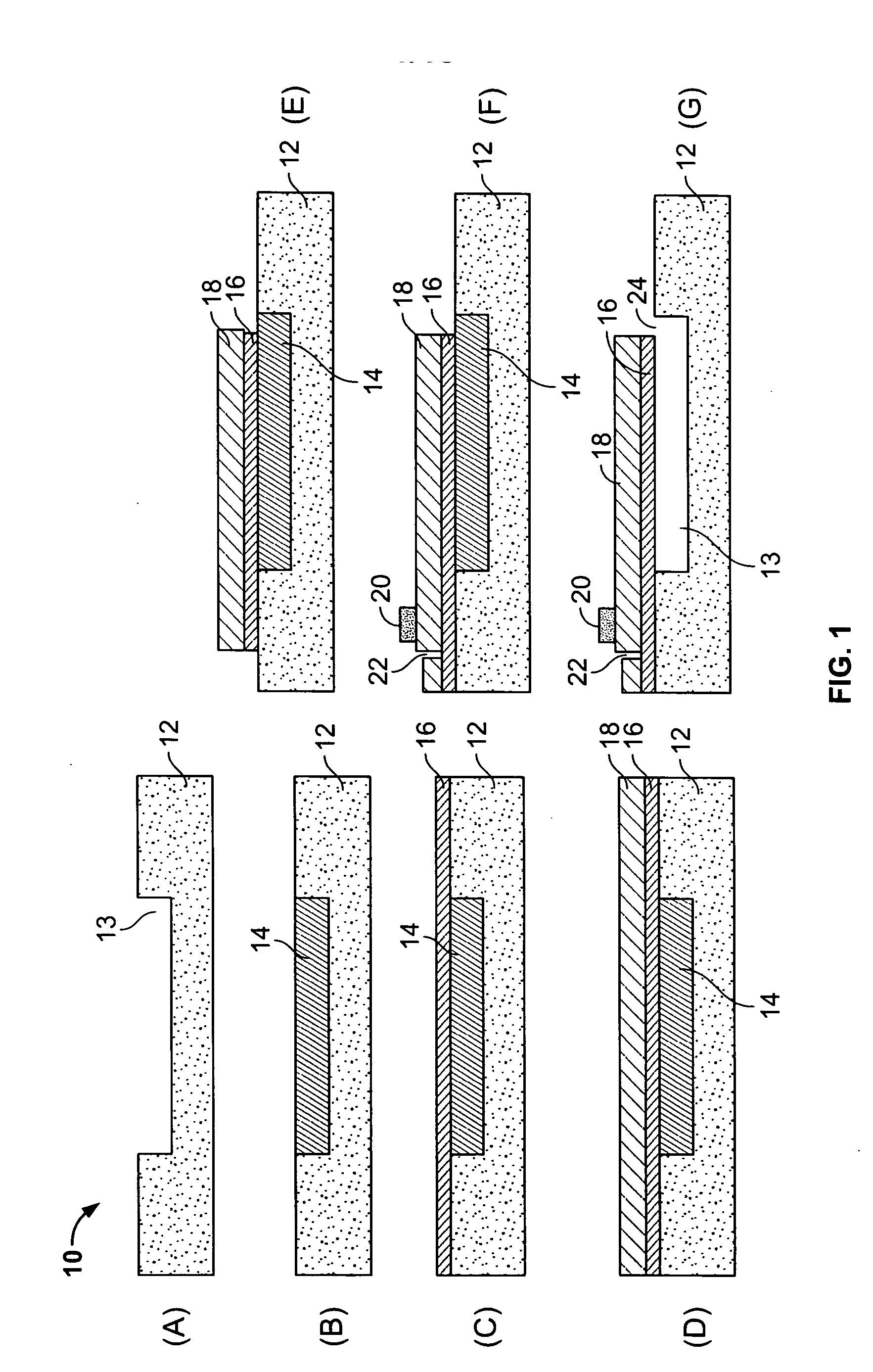
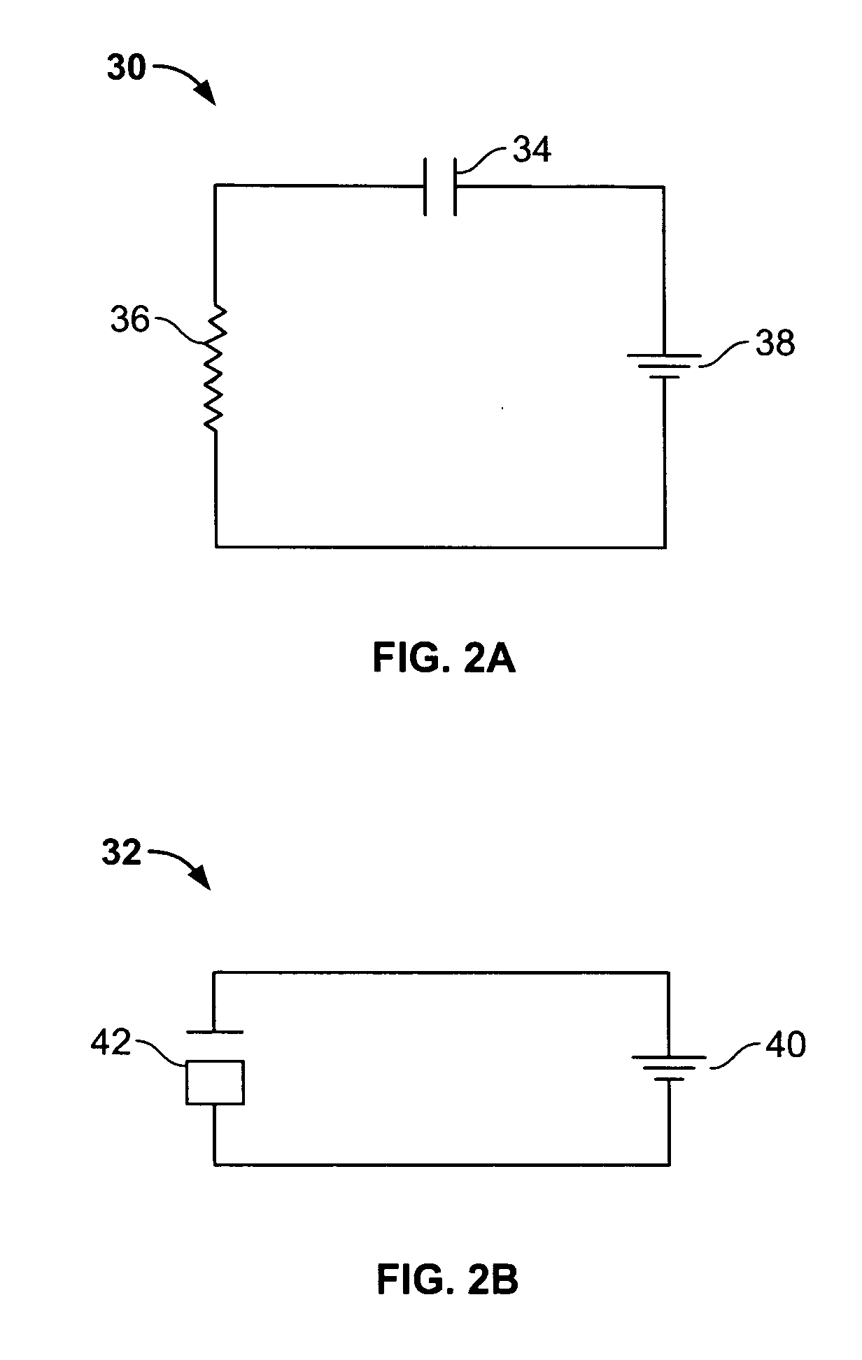
[0038] The accompanying FIGS. 1-18 depict different aspects of the present invention, including physical vapor deposition and formation of microcantilevers for use a microsensors or as drug delivery fluidic pumps, an exemplary variably resonant circuit with communicating interrogator circuits outside the body and a passive resonator sensor circuit implanted in the body, a graph depicting the relationship between RF frequency, special capacity and range, a nanothermometer, basic elements of an interactive implantable stent, a lateral accelerometer fabricated using MEMs technology, a diagrammatic galvanotactic device for generating a field gradient for imparting endothelial cell migration, a microcantilever based sensor for detection of thrombus formation and tissue thickness, a microcantilever based sensor for detection of molecular species based upon binding events, a table of different contemplated approaches to electronic biosensing, an diagrammatic device made of composite films ...


PUM


Abstract

Implantable medical devices, including stents, grafts, covered stents, catheters, patches or the like having regions of the device which are functionalized employing microelectromechanical systems that are capable of acting as electromechanical sensors or biosensors in response to either an endogenous event, such as tissue growth, biochemical binding events, pressure changes, or respond to an externally applied stimulus, such as RF energy, to cause a change in the state of the device, such as to induce an oscillation signal which may be interrogated and interpreted external the body or may generate an induced electrical or electromagnetic potential in the device to activate micromotors to effect a geometric change in the device.

Description

BACKGROUND OF THE INVENTION [0001] The present invention relates generally to the field of medical devices suitable for in vivo use, such as implantable devices, indwelling devices, catheters and delivery systems. More particularly, the present invention relates to implantable medical devices, such as endoluminal stents, that are capable of acting as sensors and / or actuators in vivo. [0002] With the advent of microelectromechanical system (MEMs) technology, manufacture of very small scale devices has become feasible. The principal application of MEMs technology has, heretofore, been in the electromechanical arts, in particular fluidics and fluid sensors. The present invention, however, adapts MEMs technology to the field of medical devices and, in particular, to the field of implantable medical devices that are designed to sense in vivo conditions, alter the geometry of the device, and / or deliver metered doses of bioactive substances in vivo. [0003] The field of implantable MEMs bas...

Claims


Application Information

Patent Timeline
Patent Type & Authority Applications(United States)
IPC IPC(8): A61B5/00A61B5/024A61B5/026A61B5/053A61FA61F2/02A61F2/06
CPCA61B5/0031A61B5/01A61B5/024A61B5/026A61F2250/0001A61B5/14532A61B5/4839A61B2562/0219A61B2562/028A61B5/053
Inventor PALMAZ, JULIO C.
Owner VACTRONIX SCI LLC
Why Eureka
Try Eureka