Thermal actuators

a technology of thermal actuators and actuators, applied in the field of micro electromechanical devices, can solve the problems of the cost of a manufactured wing semiconductor manufacturing technology device, and achieve the effects of increasing the thickness, increasing the stiffness, and increasing the stiffness

Inactive Publication Date: 2005-08-18
SILVERBROOK RES PTY LTD +1
View PDF12 Cites 3 Cited by
  • Summary
  • Abstract
  • Description
  • Claims
  • Application Information

AI Technical Summary

Benefits of technology

[0048] It is important that the arms of an actuator have sufficient stiffness to avoid buckling. For a given stiffness the efficiency of the thermal actuator is roughly inversely proportional to the mass of the actuator material. The utilization of a corrugated or non-planar structure provides for improved stiffness characteristics for a given thermal mass. The corrugations achieve a higher stiffness without increasing the thickness and thereby increasing the mass of the actuator. This provides an overall increase in efficiency. Generally, simulations indicate efficiency increases of around 50% are possible.
[0049] In the preferred embodiment, a thermal bend actuator is formed by the deposition of a single layer of titanium nitride so as to form spaced-apart actuator arms which do not coincide in a vertical plane. The advantage of utilising a single layer of out of plane actuator is that the number of layers to be deposited and patterned in the structure are substantially reduced.

Problems solved by technology

A major portion of the cost of a manufactured wing semiconductor manufacturing techniques device depends on the number of separate layers required to be deposited during fabrication.

Method used


Image

  • Thermal actuators
  • Thermal actuators
  • Thermal actuators

Examples


Embodiment Construction

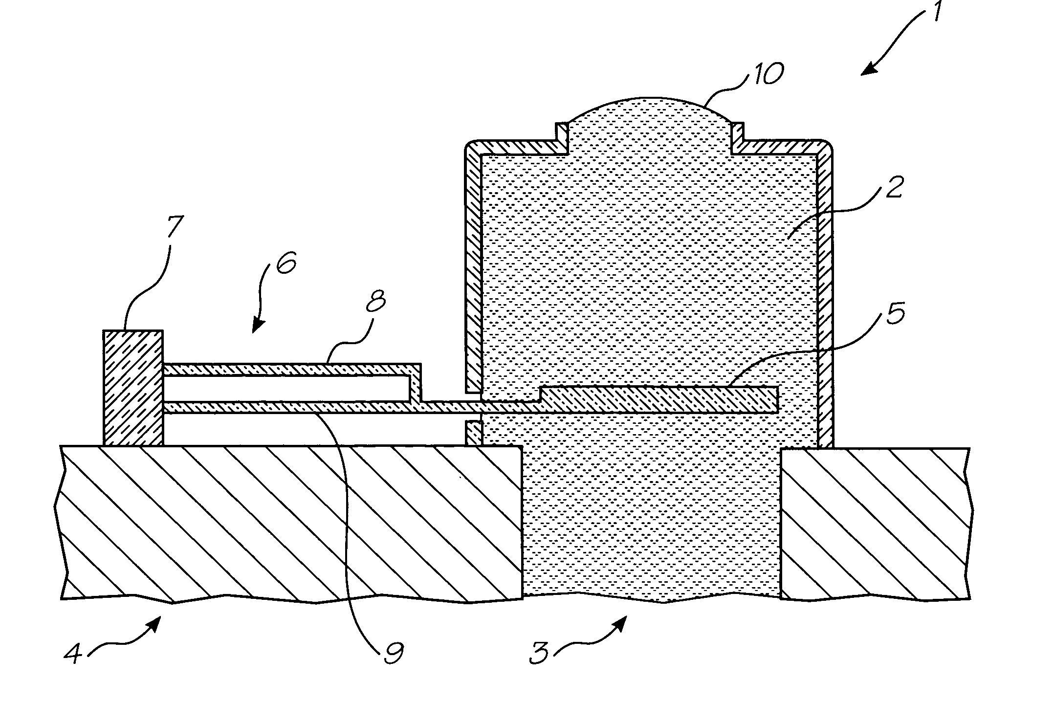
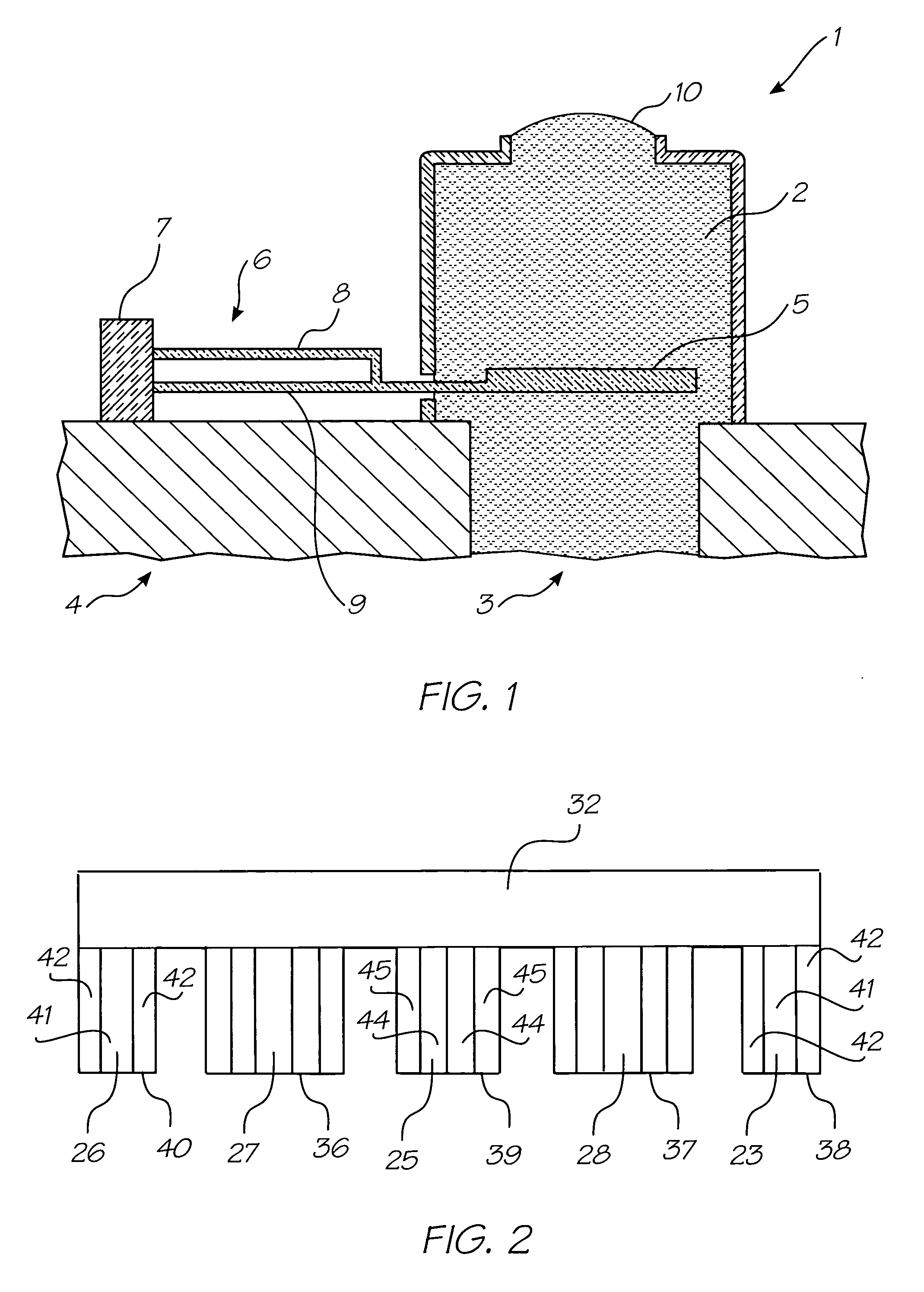
[0058] The basic operational principles of a liquid section which utilises a thermal actuator device will be explained with reference to FIG. 1. It is to be understood that the thermal actuator of the invention is not limited to use in such liquid ejection devices. As shown in FIG. 1, there is provided an ink ejection arrangement 1 which comprises a nozzle chamber 2 which is normally filled with ink so as to form a meniscus 10 around an ink ejection nozzle 11 having a raised rim. The ink within the nozzle chamber 2 is resupplied by means of ink supply channel 3.

[0059] The ink is ejected from a nozzle chamber 2 by means of a thermal actuator 7 which is rigidly interconnected to a nozzle paddle 5. The thermal actuator 7 comprises two arms 8, 9 with the bottom arm 9 being interconnected to an electrical current source so as to provide conductive heating of the bottom arm 9. When it is desired to eject a drop from the nozzle chamber 2, the bottom arm 9 is heated so as to cause rapid ex...


PUM

PropertyMeasurementUnit
depth of fieldaaaaaaaaaa
thickaaaaaaaaaa
thicknessaaaaaaaaaa

Abstract

A thermal bend actuator (6) is provided with a group of upper elongate actuator arms (23, 25, 26) and a group of lower elongate actuator arms (27, 28) which are non planar, so increasing the stiffness of the arms. The arms (23, 25, 26,27,28) may be spaced transversely of each other and do not overly each other in plan view, so enabling all arms to be formed by depositing a single layer of arm forming material.

Description

CROSS REFERENCE TO RELATED APPLICATION [0001] This is a Continuation Application of U.S. application Ser. No. 10 / 258,518 filed on Oct. 25, 2002, which is a 371 of International Application Serial No. PCT / AU01 / 00501 filed on May 2, 2001 the entire contents of which are herein incorporated by reference.FIELD OF THE INVENTION [0002] The present invention relates to the field of micro electromechanical devices such as ink jet printers. The present invention will be described herein with reference to Micro Electro Mechanical Inkjet technology. However, it will be appreciated that the invention does have broader applications to other micro electromechanical devices, e.g. micro electromechanical pumps or micro electromechanical movers. BACKGROUND OF THE INVENTION [0003] Micro electromechanical devices are becoming increasingly popular and normally involve the creation of devices on the μm (micron) scale utilising semi-conductor fabrication techniques. For a recent review on micro-mechanica...

Claims


Application Information

Patent Timeline
Patent Type & Authority Applications(United States)
IPC IPC(8): F01B29/10F02G1/04G11B5/55G11B21/08
CPCG11B5/5526
Inventor SILVERBROOK, KIA
Owner SILVERBROOK RES PTY LTD
Why Eureka
Try Eureka