Ejector cycle having multiple evaporators

a technology of ejector cycle and evaporator, which is applied in the direction of refrigeration components, transportation and packaging, light and heating equipment, etc., can solve the problems of difficulty in appropriately adjusting the flow rate of the refrigerant of the first and second evaporator, deterioration of the air conditioning feeling of the passenger, and disadvantageous increase in manufacturing costs, so as to facilitate the adjustment of the flow rate. , the effect of simple structur

Active Publication Date: 2005-08-18
DENSO CORP
View PDF16 Cites 106 Cited by
  • Summary
  • Abstract
  • Description
  • Claims
  • Application Information

AI Technical Summary

Benefits of technology

[0016] The present invention addresses the above disadvantages. Thus, it is an objective of the present invention to ease adjustment of a flow rate of refrigerant to multiple evaporators in an efficient ejector cycle having an ejector. It is another objective of the present invention to achieve easy adjustment of the flow rate of the refrigerant in the ejector cycle through use of a simple structure. It is a further objective of the present invention to provide an ejector cycle, which achieves both a simple structure and quick response while allowing flexible orientation of an ejector.

Problems solved by technology

Thus, during the refrigerator cooling operation, the passenger compartment cooling operation cannot be performed, so that air conditioning feeling of the passenger may be deteriorated.
Therefore, the manufacturing costs are disadvantageously increased.
Thus, it is difficult to appropriately adjust the flow rates of the refrigerant of the first and second evaporators 61, 62.
However, for example, when the ejector of Japanese Unexamined Patent Publication No. 2004-44906 (U.S. Patent Application Publication No. 2004 / 0007014A1) is used in the refrigeration cycle of FIG. 22, which includes the box type thermostatic expansion valve 105, the orientation of the ejector is limited.

Method used


Image

  • Ejector cycle having multiple evaporators
  • Ejector cycle having multiple evaporators
  • Ejector cycle having multiple evaporators

Examples


first embodiment

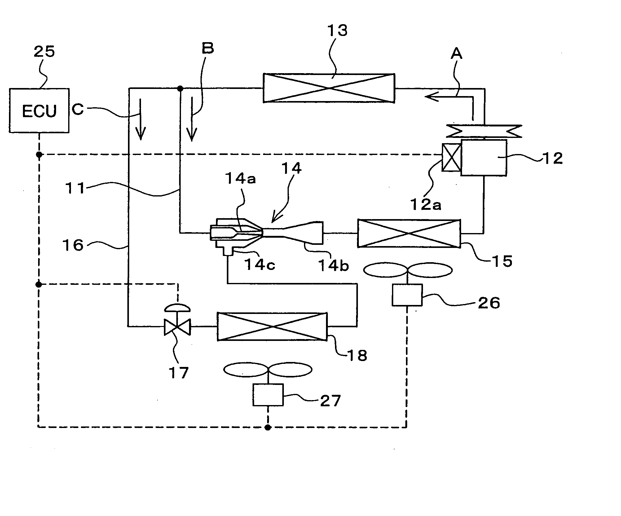
[0045]FIG. 1 shows an exemplary case where an ejector cycle according to a first embodiment of the present invention is implemented in a vehicle air conditioning and refrigerating system. The ejector cycle includes a refrigerant circulation passage 11, through with refrigerant is circulated. A compressor 12 is arranged in the refrigerant circulation passage 11. The compressor 12 draws and compresses the refrigerant supplied thereto.

[0046] In the present embodiment, the compressor 12 is rotated by, for example, a vehicle drive engine (not shown) through a belt or the like. The compressor 12 is a variable displacement compressor, which can adjust a refrigerant discharge rate through a change in its displacement. The displacement is defined as an amount of refrigerant discharged from the compressor 12 per rotation of the compressor 12. The displacement of the compressor 12 can be changed by changing an intake volume of the refrigerant in the compressor 12.

[0047] A swash plate compres...

second embodiment

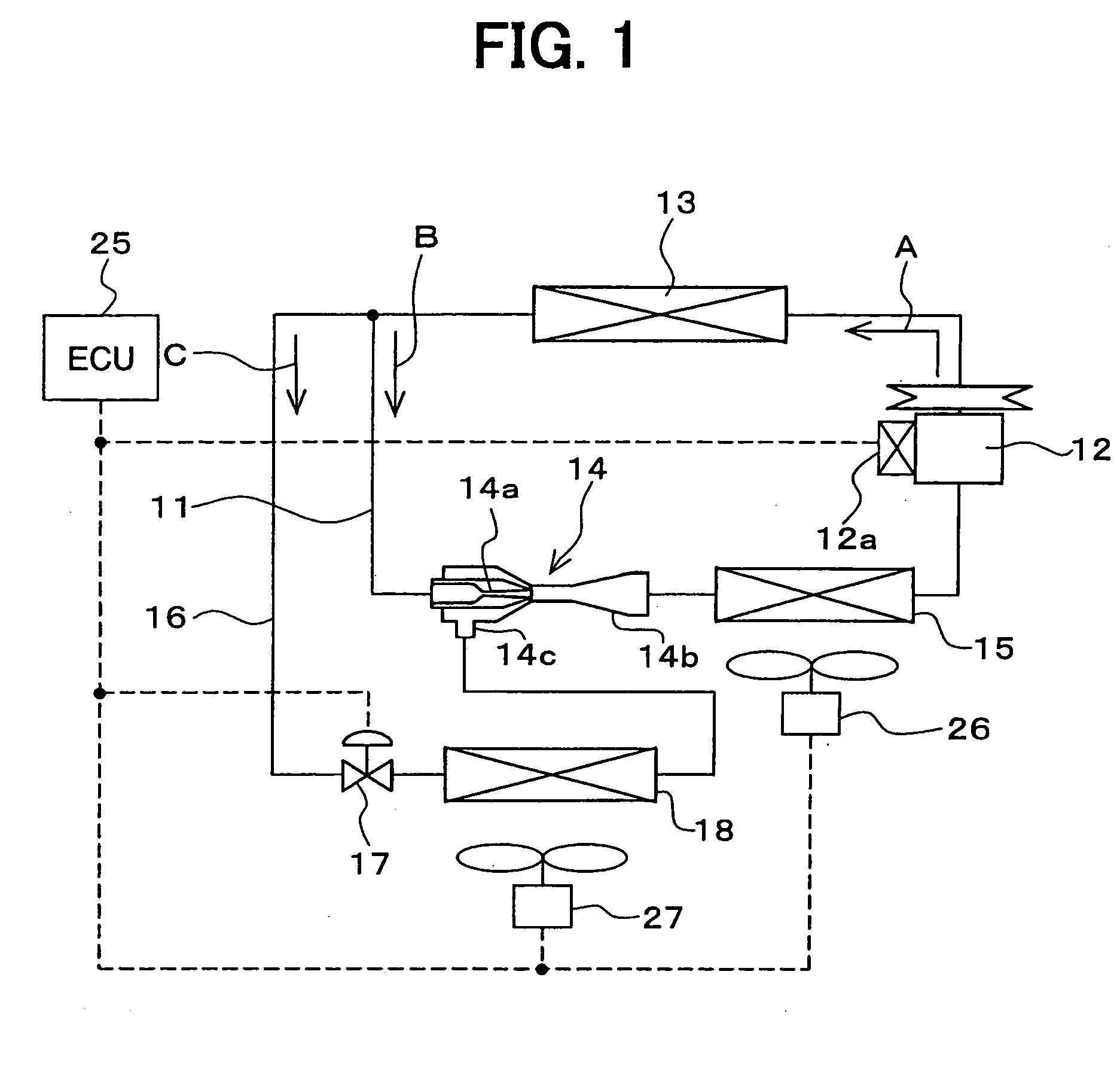
[0075]FIG. 2 shows an ejector cycle of a second embodiment, which is similar to that of the first embodiment except first and second solenoid valves (a first opening and closing means and a second opening and closing means) 19, 20. The first solenoid valve 19 opens and closes the refrigerant circulation passage 11 on the upstream side of the ejector 14. The second solenoid valve 20 opens and closes the first branched passage 16 on the upstream side of the first flow rate control valve 17. Similar to the pressure control electromagnetic device 12a of the compressor 12, the opening and closing of the first and second solenoid valves 19, 20 are controlled by a corresponding signal supplied from the ECU 25.

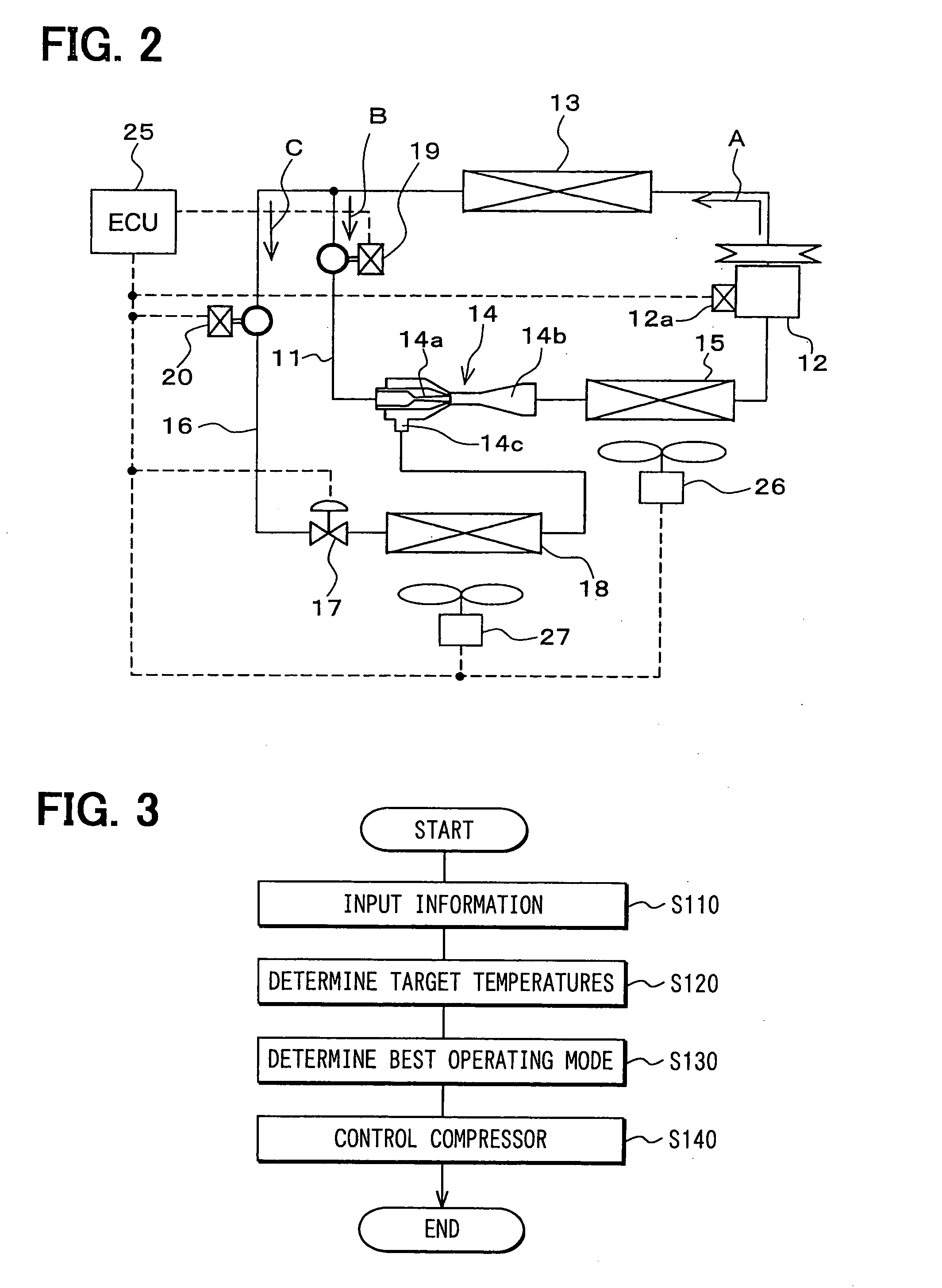
[0076] Selection of an operating mode conducted by the ECU 25 will be described with reference to FIG. 3. First, user input information, temperature information of each subject cooling space and the temperature information of each evaporator 15, 18 are inputted to the ECU 25 at step ...

third embodiment

[0088]FIG. 5 shows an ejector cycle according to a third embodiment. The ejector cycle of the third embodiment is similar to that of the second embodiment except a second branched passage 23. The second branched passage 23 connects between a portion (a branching point) of the first branched passage 16, which is on the upstream side of the first flow rate control valve 17, and a portion (a merging point) of the refrigerant passage 11, which connects between the first evaporator 15 and the compressor 12.

[0089] A second flow rate control valve (a second metering means) 24 and a third solenoid valve (a third opening and closing means) 28 are arranged in the second branched passage 23. The second flow rate control valve 24 controls the flow rate of the refrigerant and depressurizes the refrigerant. The third solenoid valve 28 opens and closes the second branched passage 23. Furthermore, a third evaporator 22 is arranged on the downstream side of the second flow rate control valve 24 in ...


PUM


Abstract

A first evaporator evaporates refrigerant, which is outputted from an ejector. A refrigerant outlet of the first evaporator is connected to a suction inlet of a compressor, which is connected to a radiator. A branched passage branches a flow of the refrigerant at a corresponding branching point located between the radiator and the ejector. The branched passage conducts the branched flow of the refrigerant to a suction inlet of the ejector. A flow rate control valve is arranged in the branched passage between a radiator and an ejector on a downstream side of the radiator to depressurize refrigerant outputted from the radiator. A second evaporator is arranged in the first branched passage.

Description

CROSS REFERENCE TO RELATED APPLICATION [0001] This application is based on and incorporates herein by reference Japanese Patent Application No. 2004-41163 filed on Feb. 18, 2004, Japanese Patent Application No. 2004-74892 filed on Mar. 16, 2004, Japanese Patent Application No. 2004-87066 filed on Mar. 24, 2004 and Japanese Patent Application No. 2004-290120 filed on Oct. 1, 2004. BACKGROUND OF THE INVENTION [0002] 1. Field of the Invention [0003] The present invention relates to an ejector cycle that includes an ejector, which serves as a depressurizing means for depressurizing fluid and which also serves as a momentum transporting pump for transporting the fluid by entraining action of discharged high velocity working fluid, so that such an ejector cycle is effectively applicable to, for example, a refrigeration cycle of a vehicle air conditioning and refrigerating system, which performs a passenger compartment cooling air conditioning operation and a refrigerator cooling operation...

Claims


Application Information

Patent Timeline
Patent Type & Authority Applications(United States)
IPC IPC(8): B60H1/32F25B5/00F25B5/02F25B9/00F25B41/00
CPCB60H2001/3297F25B5/00F25B5/02F25B9/008F25B41/00F25B2309/061F25B2600/112F25B2341/0683F25B2500/01F25B2500/18F25B2600/023F25B2600/0253F25B2341/0012B60H2001/3298F25B9/08F25B49/02
Inventor OSHITANI, HIROSHIYAMANAKA, YASUSHITAKEUCHI, HIROTSUGUKUSANO, KATSUYAIKEGAMI, MAKOTOAIKAWA, YASUKAZU
Owner DENSO CORP
Why Eureka
Try Eureka