
Roller with salient members

Inactive Publication Date: 2005-08-18
YANO HIROAKI
View PDF13 Cites 0 Cited by
  • Summary
  • Abstract
  • Description
  • Claims
  • Application Information

AI Technical Summary

Benefits of technology

[0009] The present invention provides a roll of a roller assembly that can reduce or eliminate the formation of bulges and wrinkles that create warped areas on thin substrate materials.
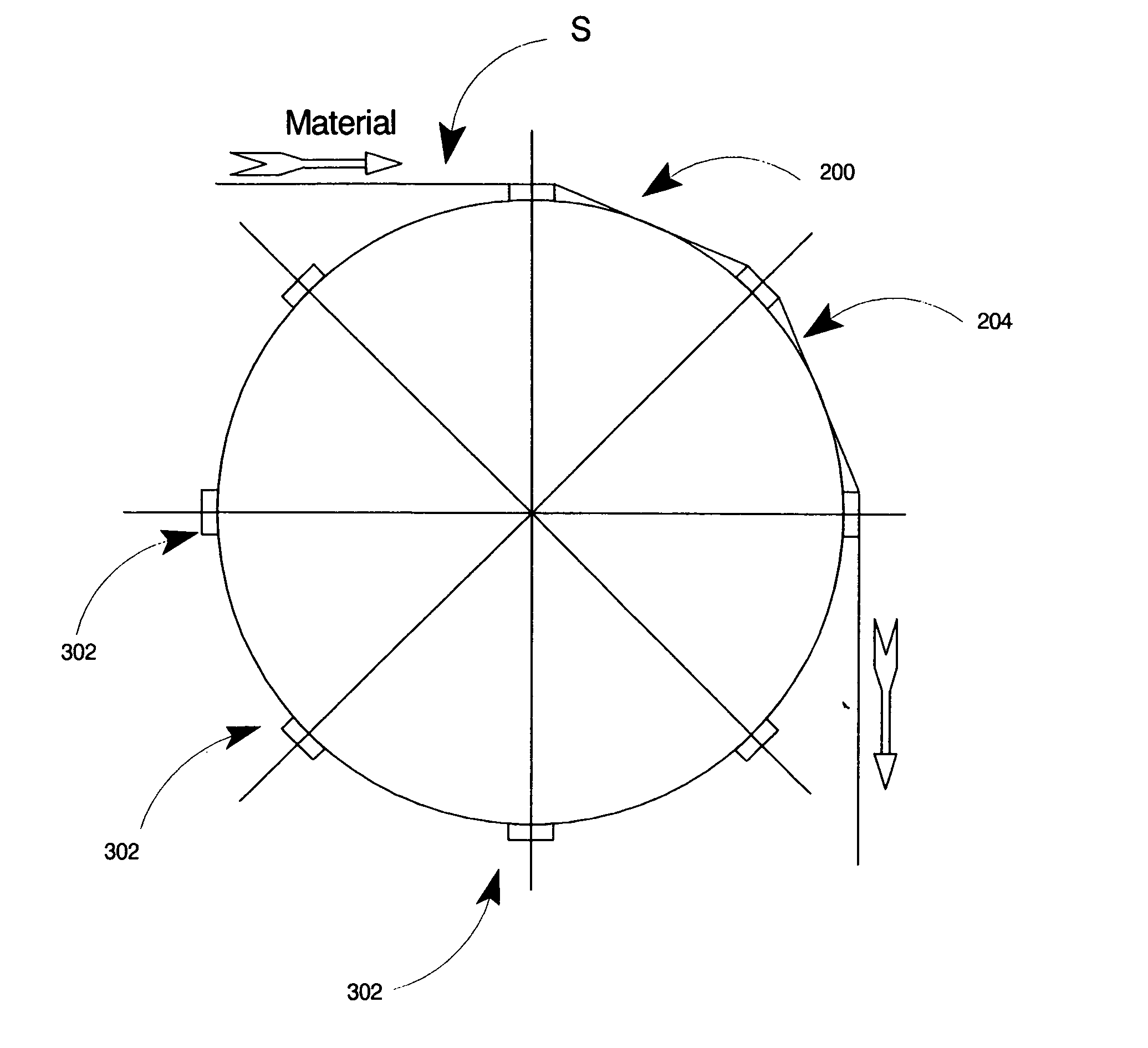
[0013] Advantageously, the sheet roller including the plurality of salient members causes fold lines to be formed across the width of the substrate material, as the substrate material is wound about the roll. The fold lines increase the tensile strength of the substrate material across the width, which increase the resistance of the substrate material to unwanted expansion due to heat and to the unwanted formation of wrinkles.
[0014] Depending on the specifications of the substrate material, the radius of the fold lines, the interval between the fold lines and the pitch of the fold lines can be tailored by modifying the size and shape of the salient members. Fold lines can be formed on the top and bottom surfaces of the substrate material to further increase the strength of the material.
[0015] Beneficially, if the substrate material can be wound through the roll without forming warped areas, the substrate material is in a better condition for being subjected to various forms of deposition, such as vacuum deposition and other deposition techniques at ambient pressure and temperature, which reduces or eliminates detriments, such as the formation of rails.
[0016] The fold lines formed by the present invention are very small and therefore cannot be detected by the naked eye. Moreover, the fold lines do not cause a detriment to any deposition processes. In addition, the fold lines are easily removed from the substrate material with minimal further processing.

Problems solved by technology

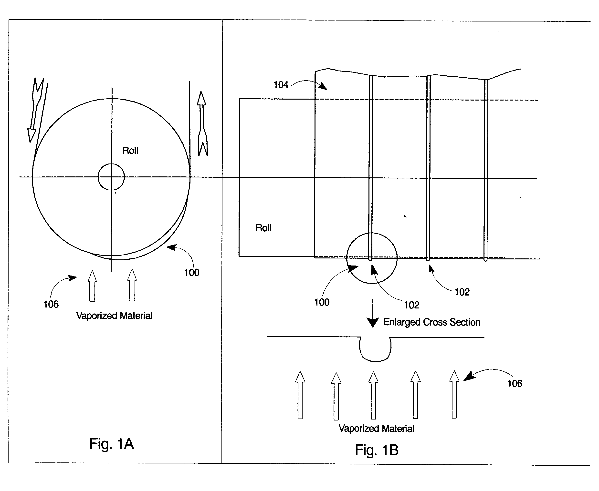
Unfortunately, rolled thin substrates are easily warped during processing.
As shown in FIG. 1B, the bulged area is not flat, thus, causing a portion of the bulged area to be inadequately covered with vaporized material.

Method used


Image

  • Roller with salient members
  • Roller with salient members
  • Roller with salient members

Examples


Embodiment Construction

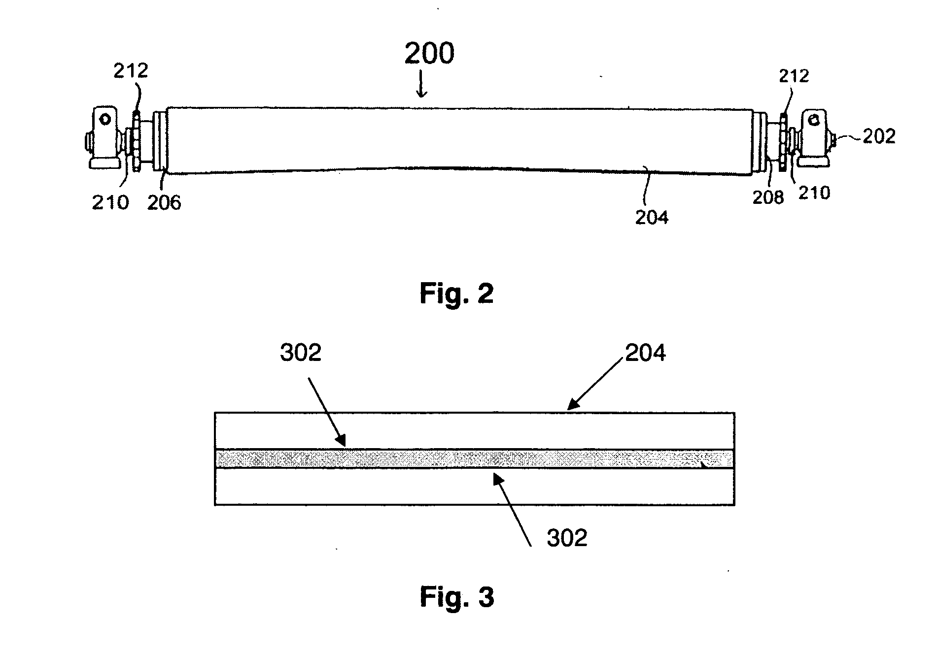
[0027]FIG. 2 is a simplified illustration of roll 200, which includes a roller shaft 202 and a sheet roller 204. It should be understood that the construction of roll 200 can be accomplished using any conventional parts and manufacturing techniques.

[0028] In one exemplary embodiment with no intent to limit the invention, as FIG. 2 shows, sheet roller 204 can be rotatably mounted on a plurality of casings housing bearings on roller shaft 202. Sheet roller 204 may be configured to have many shapes, for example, sheet roller 204 can have an outer circumference that is constant or, which gradually increases or decreases progressively in an axial direction from its central part toward its opposite end parts.

[0029] In this embodiment, end flanges 206 can be fitted in the end parts of sheet roller 204. Set flanges 208 can be mounted on the external sides of the end flanges. Set sleeves 210 can be fitted onto roller shaft 202. Gears 212 may be used to transmit a drive force for rotation o...


PUM


Abstract

A roll for feeding substrate material, which includes a sheet roller, which has a circumference and a surface layer, configured to rotate about a first axis. A plurality of salient members are disposed on the surface layer to extend along the first axis at intervals about the circumference. Each of the plurality of salient members is configured to cause a fold line to form across a width of the substrate material, which is substantially perpendicular to a direction of travel of the substrate material.

Description

BACKGROUND [0001] 1. Field of the Invention [0002] The present invention relates to a roll and, more specifically, to a roll which includes salient members for forming fold lines on a substrate material. [0003] 2. Related Art [0004] Deposition systems have been created for the deposition of metal, oxides, or similar materials onto continuously wound thin substrates, such as paper, plastic film, metal foil and the like. The wound or rolled thin substrates can be used, for example, as packaging material, capacitors and magnetic tape. [0005] Unfortunately, rolled thin substrates are easily warped during processing. As illustrated in FIG. 1A, typically, the warped area 100 may be created by the expansion of the substrate (i.e. bulging) which occurs when the thin substrate is exposed to heat or when the thin substrate has formed wrinkles, during the rolling process. [0006] Wrinkles or bulges 102 formed on the thin substrate 104 make it difficult to properly and adequately deposit vaporiz...

Claims


Application Information

Patent Timeline
IPC IPC(8): B65H20/00B65H27/00
CPCB65H2404/1118B65H27/00
Inventor YANO, AKECHI
Owner YANO HIROAKI
Learn More