Supercharge Your Innovation With Domain-Expert AI Agents!

Forward inboard retracting main landing gear

Active Publication Date: 2005-08-18
SUPERSONIC AEROSPACE INT
View PDF11 Cites 15 Cited by
  • Summary
  • Abstract
  • Description
  • Claims
  • Application Information

AI Technical Summary

Benefits of technology

[0006] What is desired is a landing gear that reduces the amount of storage volume while avoiding interference between the landing gear and surrounding structures. What is further desired is a simple landing gear that avoids points of failure associated with shortening structures of the main landing gear strut such as folding and hinge structures.
[0007] In accordance with various embodiments of the disclosed aircraft landing system, a main landing gear comprises a continuous linear strut, unbroken by bends or folds that is connected to an aircraft wing and stows forward and inward so that the landing gear truck is compactly contained within the aircraft fuselage. The continuous linear strut eliminates folds and hinges in the support structure that otherwise increase complexity, cost, and maintenance burden. Avoidance of hinges and bends in the support beam also reduces or minimizes the likelihood of strut breakage and failure that may prevent the gear from extending. Forward and inward stowing of the landing gear reduces lateral sweep of the gear when retracted so that landing gear on both sides of the aircraft do not interfere upon retraction, even for long landing gear.
[0012] In an illustrative embodiment, a four-wheel truck arrangement reduces wheel and tire size and spreads truck volume over an extended length to reduce stowage cross-sectional area. The reduction is cross-sectional area of the truck arrangement can be exploited to attain a low wave drag and to produce a desirable sonic boom signature, improving environmental aspects of aircraft performance. The landing gear also enables or facilitates a relatively forward position of gear stowage volume and thus a reduction in fuselage volume behind the landing gear, characteristics that also improve wave drag and sonic boom reduction considerations.
[0013] The forward retraction aspect of the landing gear is highly desirable in an aircraft configured so that the landing gear length from trunnion to axle in an uncompressed position is longer than the available distance from the trunnion to the vehicle centerline for stowing the landing gear directly inboard. In various embodiments, the identified configuration can be useful for attaining aerodynamic and sonic boom suppression goals. The continuous, nonbending, and nonfolding aspects of the forward retracting main landing gear are further desirable to avoid or eliminate weight, reduce cost, simplify maintenance procedures, and increase reliability. Forward retraction and storage of the landing gear, thereby avoiding direct inboard stowing, reduces or eliminates additional folding mechanisms and or shrink links. Avoidance of shrink links is desirable to avoid shrink link failure in the retracted position that could jam a wheel truck and prevent gear extension.
[0015] In various embodiments, an aspect of an aircraft that utilizes the disclosed main landing gear is a substantial dihedral or gulling incorporated into the wing inboard of the engines, most pronounced at the wing trailing edge. The dihedral or gulling is created by twisting or cambering the wing for low sonic boom and low induced drag while preserving a tailored local wing contour where the main landing gear retracts. In some embodiments, the wing includes leading edge Krueger flaps with the leading edge of the wing extending in an essentially straight line to facilitate using a simple hinge line that accommodates Krueger flaps along approximately the full-span of the wing.

Problems solved by technology

Increasing wing sweep further complicates landing gear design by reducing space available to stow the gear and complicating gear form and structure.
One challenge in design and implementation of a nose wheel tricycle landing gear configuration relates to storage of the gear when retracted.
Some aircraft, for example the Concorde, use main landing gear that shorten during the retraction process because the gear would otherwise be too long to fit into storage bays.
A disadvantage of the shortening gear is the introduction of folding linkages and hinges as points of failure.

Method used


Image

  • Forward inboard retracting main landing gear
  • Forward inboard retracting main landing gear
  • Forward inboard retracting main landing gear

Examples


Embodiment Construction

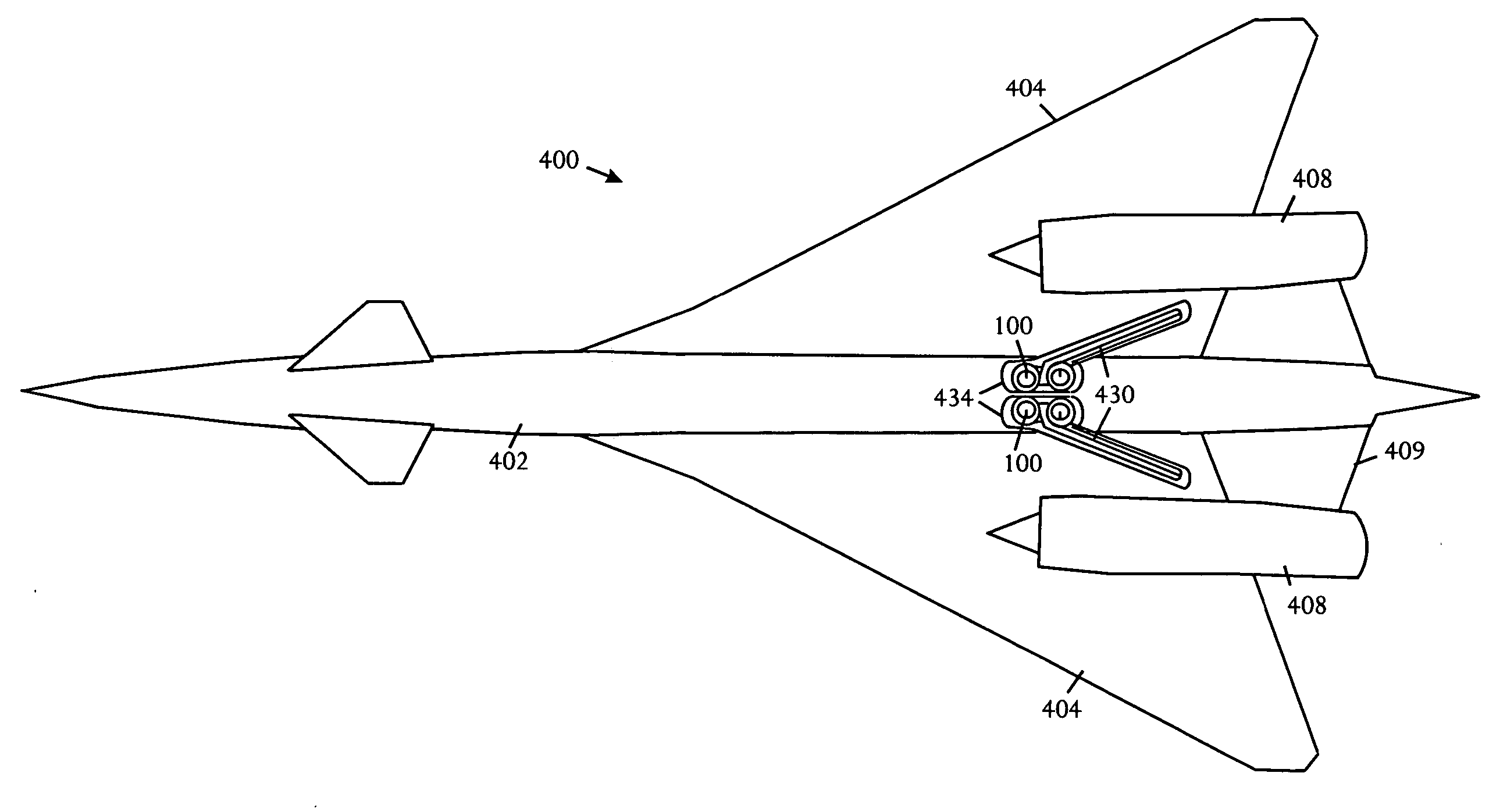
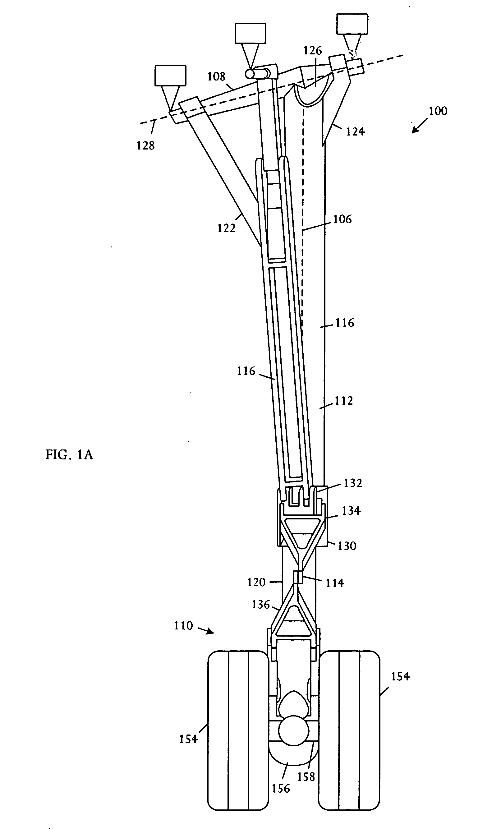
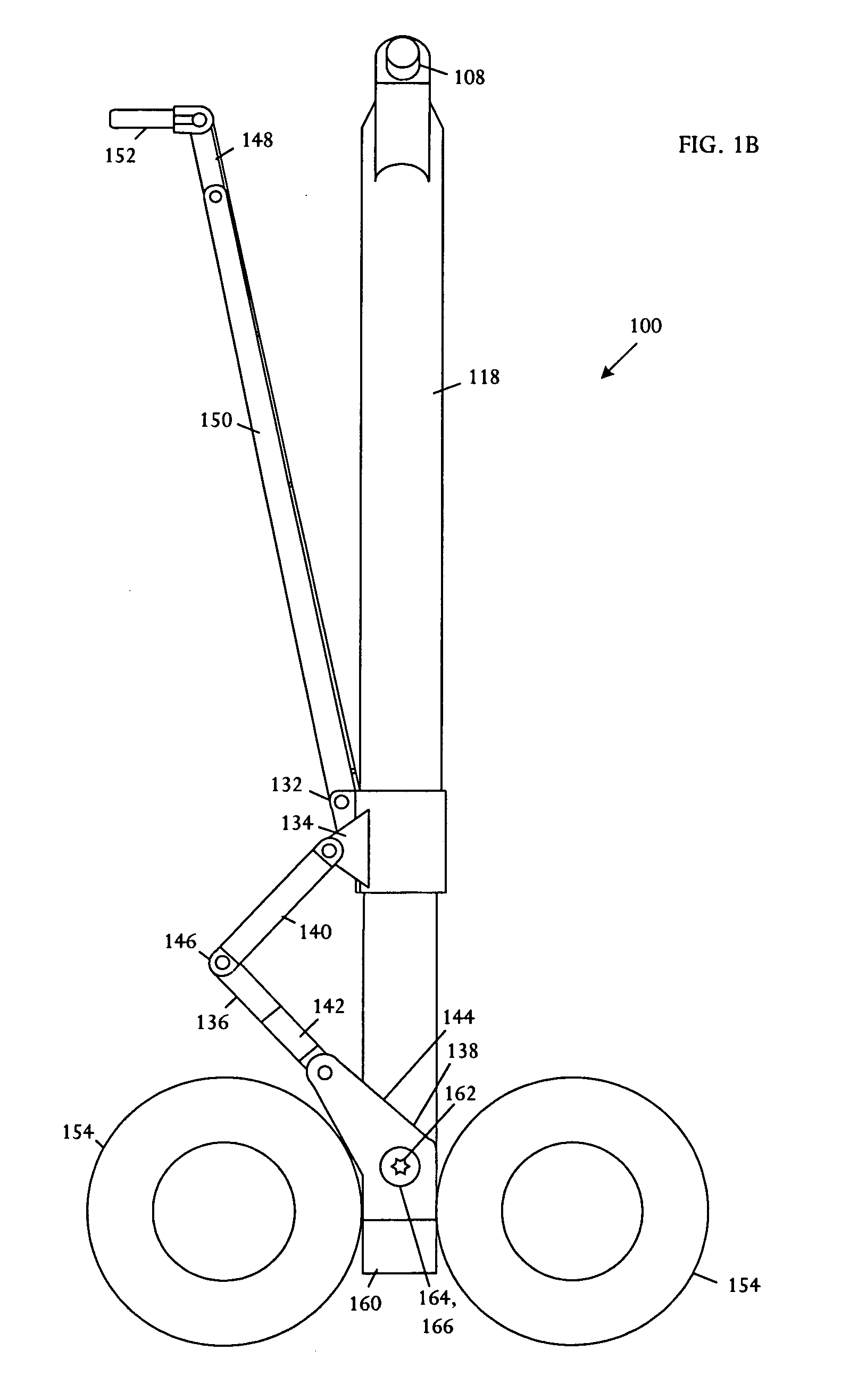
[0024] Referring to FIGS. 1A, 1B, and 1C, schematic pictorial diagrams show front, side, and top views of an extended main landing gear 100. FIGS. 2A, 2B, and 2C show respective front, side, and plan views of the main landing gear 100 when retracted. The illustrative main landing gear 11[0025]0 comprises a four-wheel truck 100, a shock strut 112, a collar / scissor link assembly 114, and a drag strut assembly 116. The shock strut 112 is substantially straight; having no folding structures, shrink linkages, or hinges that would otherwise be used to shorten the strut upon retraction. By eliminating structures that shorten the strut on retraction, the main landing gear 100 minimizes or reduces the risk that the landing gear will fail to extend.

[0026] The shock strut 112 is a nonfolding, nonhinged structure, having a length that is essentially fixed throughout the retraction and extension cycle. The shock strut 112 further comprises collinear telescoping inner 120 and outer 118 cylinders...


PUM


Abstract

An aircraft landing gear is movable between a retracted position and an extended position. The aircraft landing gear comprises a nonfolding, nonhinged shock strut that extends along a shock strut axis from a proximal end to a distal end and remains at an essentially constant length throughout an extension / retraction cycle. A trunnion is coupled to the proximal end of the shock strut and capable of pivoting in combination with the shock strut about a canted trunnion axis. A multiple-wheel truck is coupled to the distal end of the shock strut. A drag strut is coupled to the shock strut at a position intermediate to the shock strut proximal and distal end and is capable of folding as the landing gear is retracted and straightening as the landing gear is extended. The canted trunnion axis is canted so that the shock strut retracts in a forward and inboard direction and extends downward and outboard.

Description

BACKGROUND OF THE INVENTION [0001] Characteristics of aircraft structure and usage, including geometry, weight, and purpose determine appropriate structural, kinematic, and positioning characteristics of landing gear. Landing gear positioning is fundamentally based on stability considerations during high-stress operations including landing, takeoff and taxiing, when the aircraft should avoid tip back or tip over. Kinematics relates to behavior of landing gear elements that are used to retract and extend the landing gear. Landing gear kinematics largely concern geometry of landing gear in deployed and retracted positions, in combination with the swept volume consumed during retraction and deployment. [0002] Landing gear design for modern aircraft takes into consideration load distribution, stowage space, stowage proximity, and gear kinematic capability to transfer the gear between stowed and deployed positions. Main landing gear are commonly wing-mounted and body-stowed. Heavy aircra...

Claims


Application Information

Patent Timeline
IPC IPC(8): B64C25/14
CPCB64C25/14
Inventor QUAYLE, BRIAN
Owner SUPERSONIC AEROSPACE INT
Features
  • R&D
  • Intellectual Property
  • Life Sciences
  • Materials
  • Tech Scout
  • Unparalleled Data Quality
  • Higher Quality Content
  • 60% Fewer Hallucinations
Learn More