Optical spectrometer

a spectrometer and optical technology, applied in the field of optical spectrometers, can solve the problems of low efficiency of diffraction from a grating, diffractive mutual interference, etc., and achieve the effects of reducing efficiency, uniform and reproducible spectral resolution, and minimizing wavelength dependence of spectral resolution

Inactive Publication Date: 2005-08-18
RIVER DIAGNOSTICS
View PDF4 Cites 19 Cited by
  • Summary
  • Abstract
  • Description
  • Claims
  • Application Information

AI Technical Summary

Benefits of technology

[0012] It has moreover been discovered that to achieve a high, uniform and reproducible spectral resolution over the wavelength interval of interest, it is desirable that the diffracted light should preferably be diffracted substantially perpendicular to the plane of the grating. Resolution depends on the cosine of the angle between the direction of diffraction and the normal to the plane of the grating. When the light in the wavelength interval of interest is diffracted in a range of directions for which the change in the cosine of this angle is minimal, the wavelength dependence of the spectral resolution is minimized. Moreover, for a given angle of incidence of incoming light on the grating, resolution is then at a maximum. Rotation of the direction of polarization so that both polarization components reach the grating at least once with their polarization direction mostly parallel to the main direction is especially advantageous in this case, since diffraction in the perpendicular direction requires incidence under an angle, which would otherwise lower efficiency.
[0013] Furthermore, in order to achieve high efficiency, it is desirable that only one order of wavelength-dependent diffraction occurs. Thus, no energy is lost to orders of diffraction that do not reach the intensity-detection device; or if it did, that would have to be analyzed separately. To realize this in combination with diffraction close to the normal to the grating plane, the incoming light has to be incident at a relatively small angle relative to the plane of the grating, which will be termed a “grazing angle,” which is typically in the range of 60-85 degrees with respect to the normal of the plane of the grating, depending on the wavelength range of interest. At larger angles, an impractically large grating and lens for collection of diffracted light are needed. For smaller angles, the direction of first-order diffracted light in the wavelength range for which no second-order diffraction can occur, deviates from perpendicular diffraction as described above to the extent that the advantage of substantially wavelength-independent spectral resolution as a function of wavelength obtained with substantially perpendicular diffraction is lost.
[0014] Measures to improve alignment of polarization components in the incoming light to the main direction of the grating are especially advantageous in this case, since diffraction in the perpendicular direction in combination with grazing incidence otherwise lowers diffraction efficiency of commonly used gratings, such as, e.g., holographic gratings.
[0015] The use of grazing incidence has the effect that the area of the grating that is illuminated with the incoming light is larger than the required area of the optical elements in the path of the incoming light before the light reaches the grating (since these elements are generally perpendicular to the direction of travel of the light). This means that relatively small, low-cost optical elements can be used in that path. This holds, in particular, for the polarization rotation elemen

Problems solved by technology

The grooves result in diffractive mutual interference effects that concentrate reflected or transmitted electromagnetic energy in discrete directions for which constructive interference occurs.
Unfortunately, under certain circumstances, the efficiency of diffraction from a grating is not very high, or only high for

Method used


Image

  • Optical spectrometer
  • Optical spectrometer
  • Optical spectrometer

Examples


Embodiment Construction

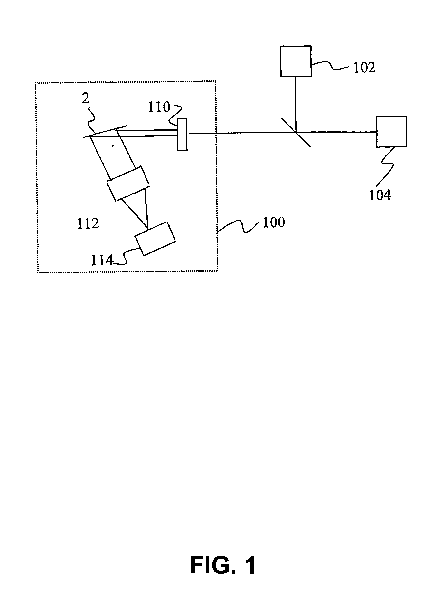
[0032]FIG. 1 schematically shows a spectrometer 100. Spectrometer 100 contains entrance optics 110, a grating 2, detection optics 112 and a detector 114. Spectrometer 100 serves to measure the intensity of light as a function of wavelength. An example of an application of such a spectrometer 100 is in Raman scattering experiments where the wavelength dependence of intensity of inelastically scattered light (scattered light with wavelengths other than the light incident on a specimen) is measured. By way of example, FIG. 1 schematically shows a Raman measurement configuration with a preferably monochromatic light source 102 and a specimen 104. In operation, light source 102 produces light to illuminate specimen 104, which scatters the light. The scattered light is fed to spectrometer 100, which measures the intensity of the scattered light as a function of wavelength (or, equivalently, frequency).

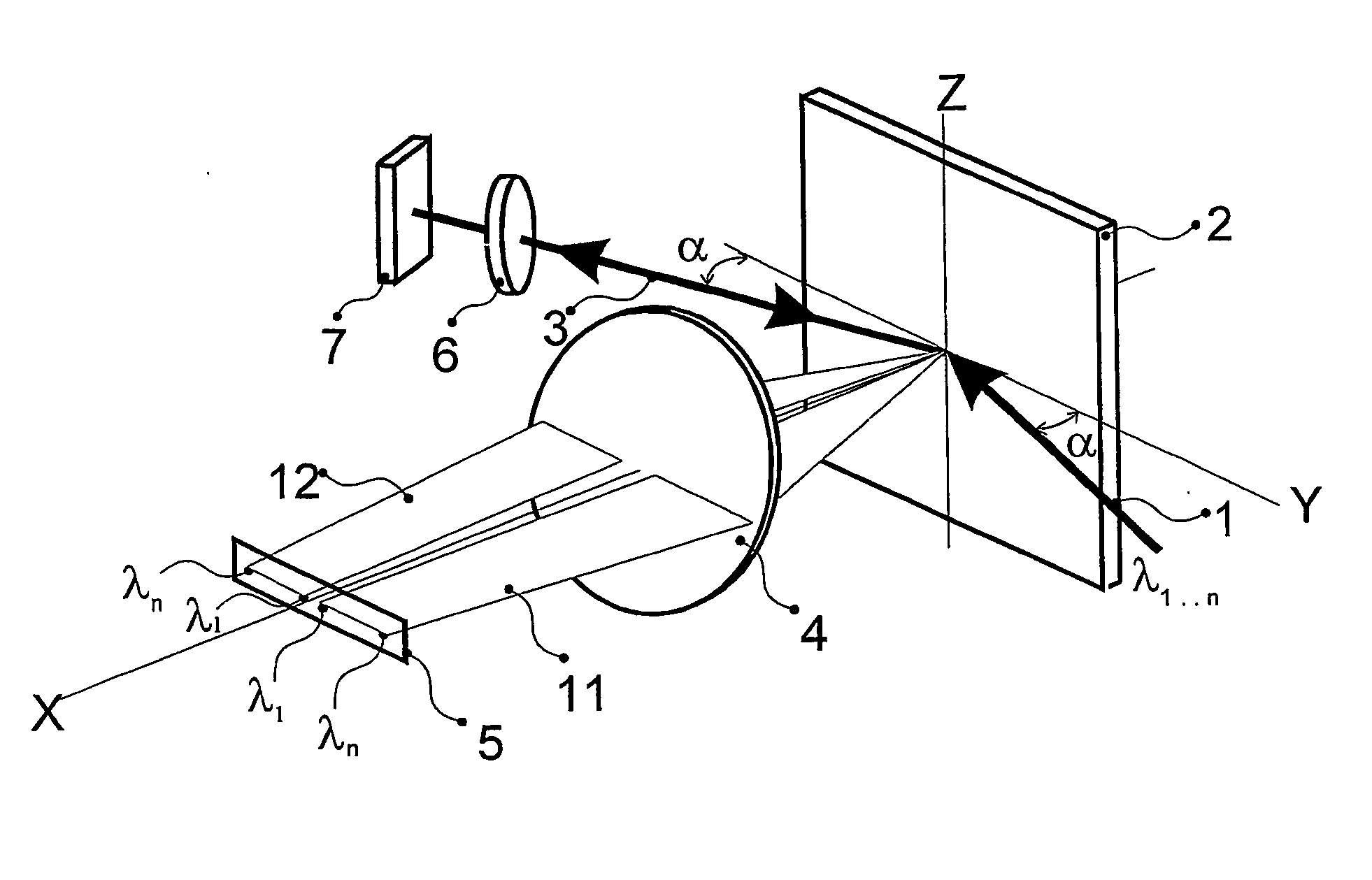
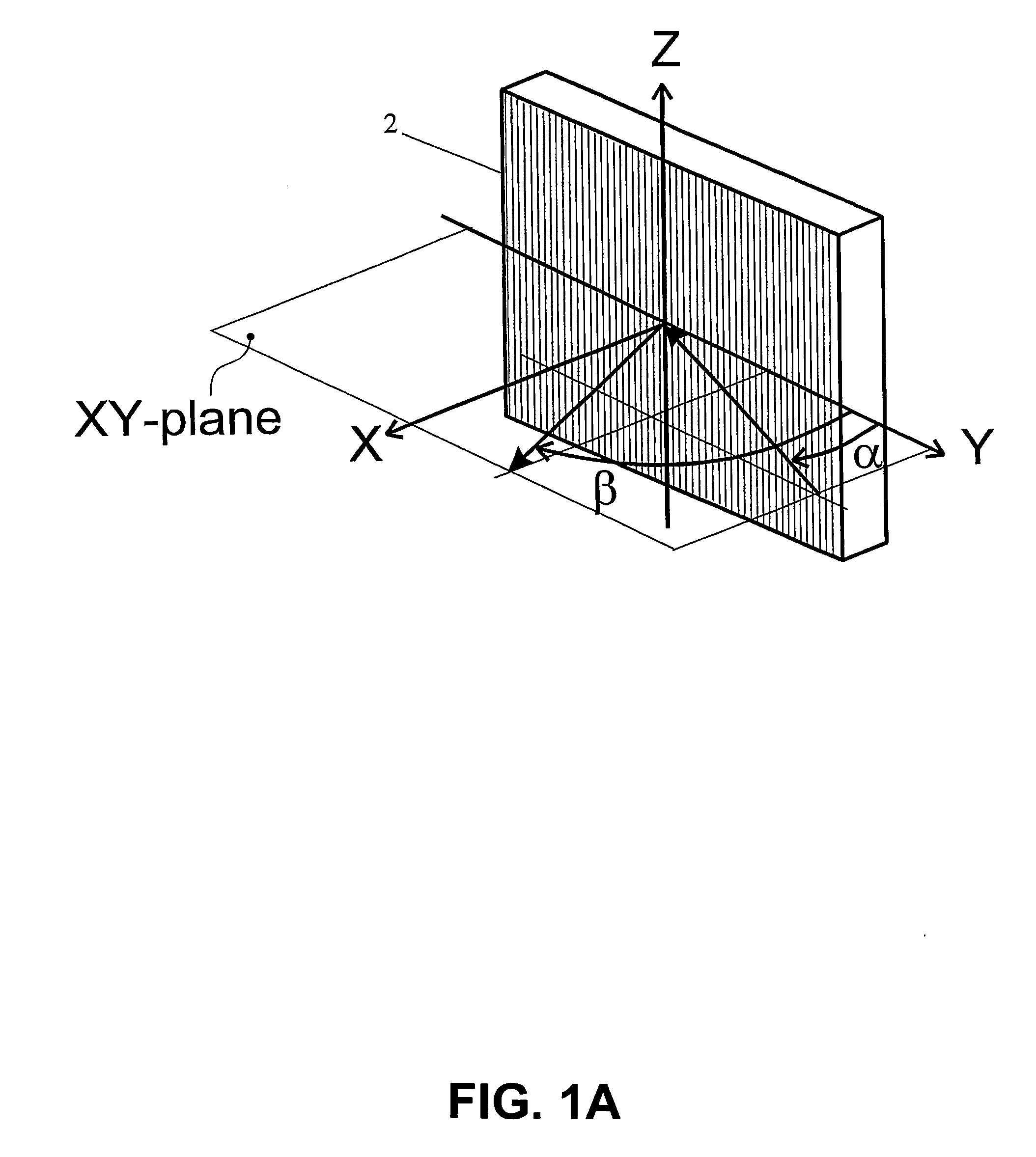
[0033]FIG. 1A shows a reflection grating 2 for use in a spectrometer. The grating has a...


PUM


Abstract

Incoming light is spectrally analyzed by diffracting the incoming light with a grating. At least a part of the incoming light is split off so that this part contains mainly one polarization component of the incoming light. It is ensured that this split-off part and a remaining part of the incoming light reach the grating with their polarized component mainly parallel to a main direction of polarization which is diffracted with maximal efficiency by the grating. For this purpose, at least the split-off part is diffracted after being passed through a polarization rotating element.

Description

CROSS-REFERENCE TO RELATED APPLICATION [0001] This application is a continuation of PCT International Patent Application No. PCT / NL2002 / 000468, filed Jul. 12, 2002, designating the United States of America, and published, in English, as PCT International Publication No. WO 2204 / 008089 A1 on Jan. 22, 2004, the contents of the entirety of which is incorporated by this reference.TECHNICAL FIELD [0002] The invention relates to an optical spectrometer. BACKGROUND [0003] A well-known type of optical spectrometer uses a grating to diffract light. A grating is, for example, an array of fine, substantially parallel, substantially equally spaced grooves (“lines” or “rulings”) on a reflecting or transparent substrate. The grooves result in diffractive mutual interference effects that concentrate reflected or transmitted electromagnetic energy in discrete directions for which constructive interference occurs. These directions are wavelength dependent, except for the direction of straight transm...

Claims


Application Information

Patent Timeline
IPC IPC(8): G01J3/18G01J3/447
CPCG01J3/447G01J3/18
Inventor PUPPELS, GERWIN JAN
Owner RIVER DIAGNOSTICS
Why Eureka
Try Eureka