
Instruments and methods for accessing an anatomic space

an anatomic space and instrument technology, applied in the field of instruments and methods for accessing and expanding anatomic space, can solve the problems of unattractive scars, carries additional complications, and thoracic muscle and rib injuries

Inactive Publication Date: 2005-08-18
MEDTRONIC INC
View PDF41 Cites 198 Cited by
  • Summary
  • Abstract
  • Description
  • Claims
  • Application Information

AI Technical Summary

Benefits of technology

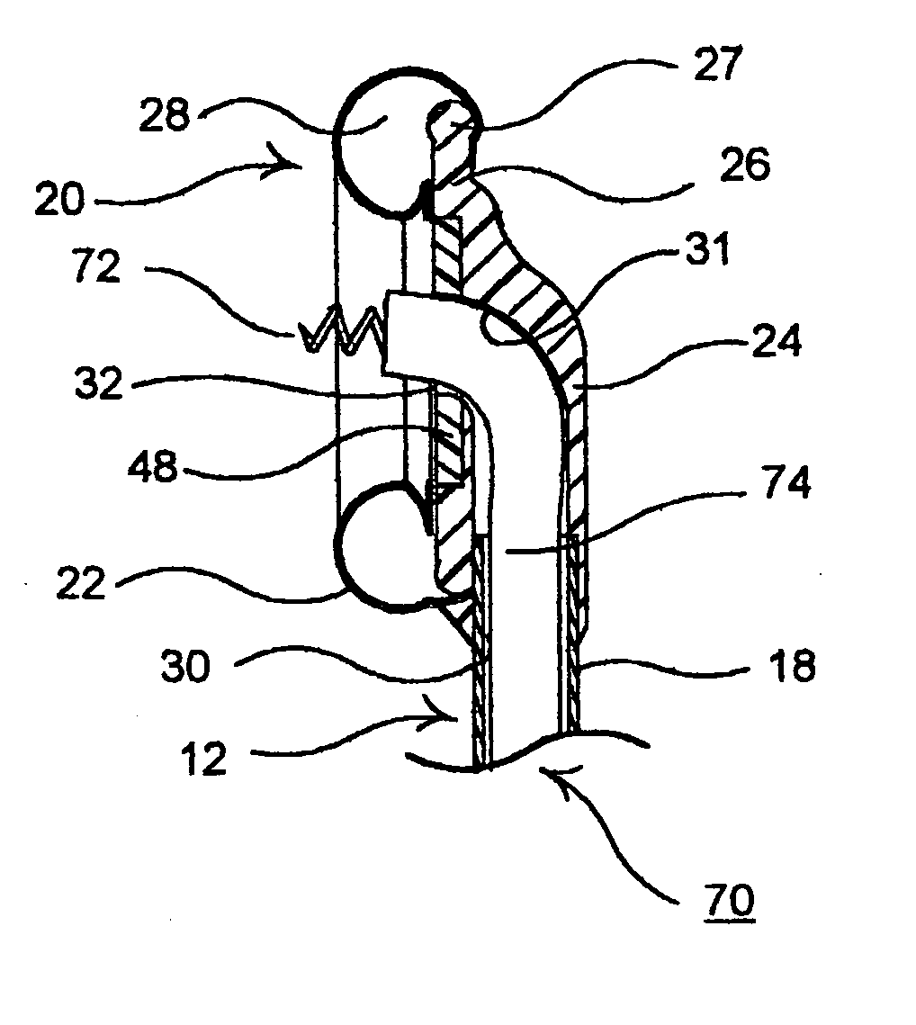
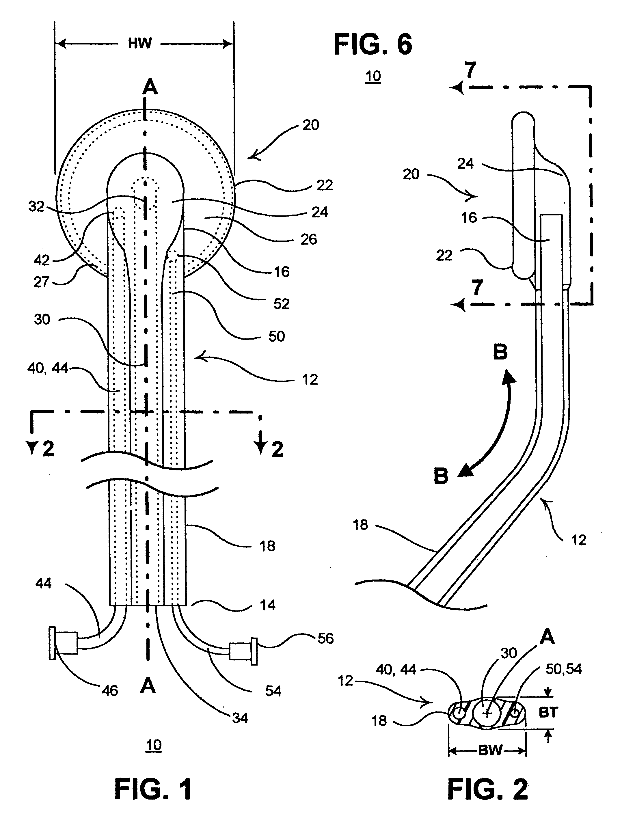
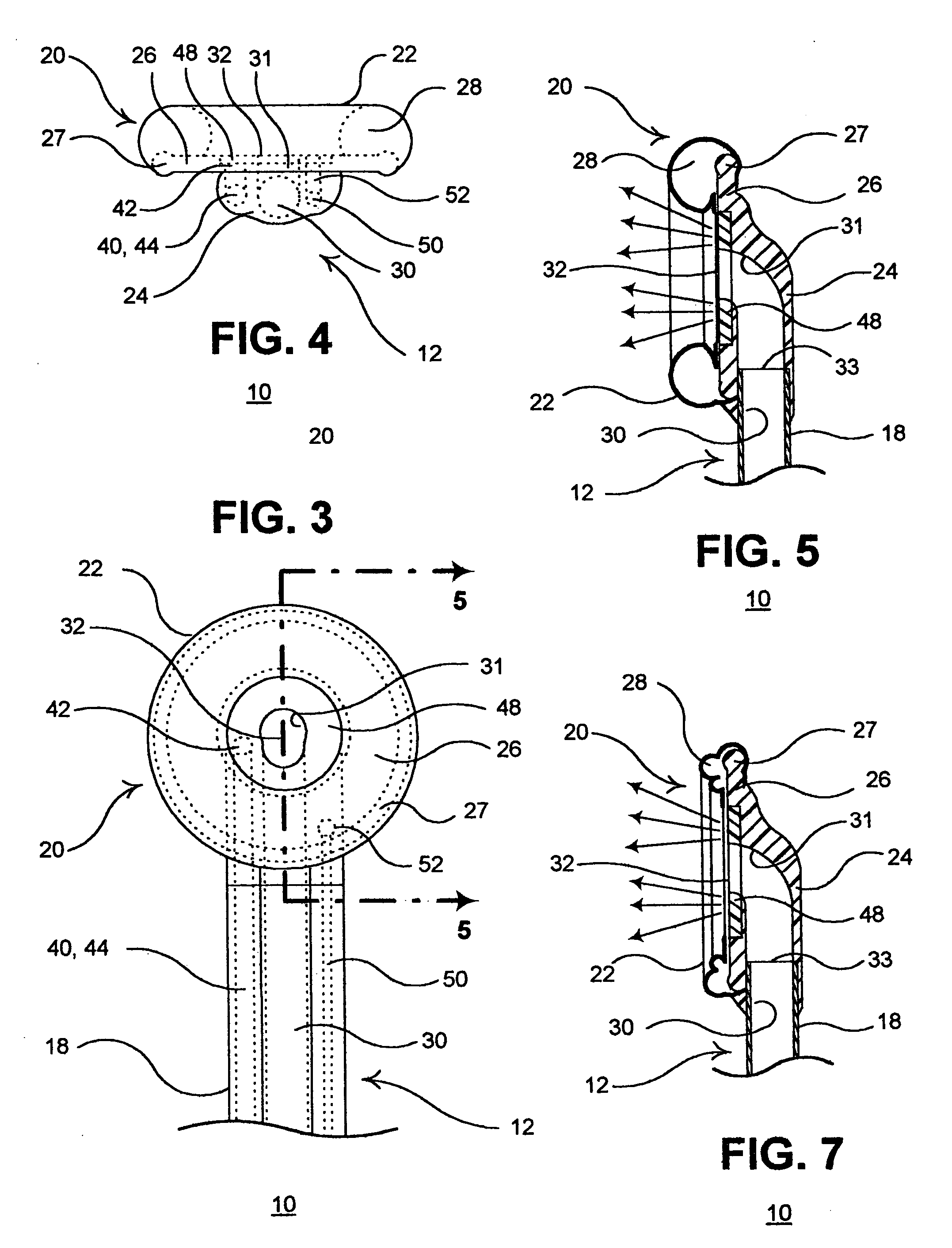
[0020] In a preferred embodiment, the elongated instrument body is formed of an elastomer extending between the instrument body proximal end and the instrument body distal end, the elongated instrument body having a instrument body axis, a instrument body width in a width direction with respect to the instrument body axis, and a instrument body thickness in a thickness direction substantially orthogonal to the width direction. The instrument body width exceeds the instrument body thickness enabling bending of the instrument body in the thickness direction and resisting bending of the instrument body in the width direction. The distal header coupled to the instrument body distal end comprises a header body enclosing a lumen elbow that extends through a 90° bend from the distal end of the instrument body working lumen and a plate extending laterally of the instrument body axis in the width direction to a plate rim. The plate has a first plate side bounded by the plate rim, and the working lumen exit port of the distal header lumen is in the first plate side. The inflatable balloon is mounted to the plate substantially surrounding the working lumen exit port. The plate rim is relatively blunt and substantially atraumatic when applied against body tissue, but the plate rim possesses sufficient rigidity to maintain the plate shape and to function as an obdurator or tunneling instrument when advanced into an anatomic space to separate tissue layers and anatomic surfaces.
[0021] In a further preferred embodiment, the balloon is formed of distal and proximal balloon segments that can be selectively separately inflated and deflated. For example, the proximal balloon segment can be inflated while the distal balloon segment is deflated to provide a distal opening facilitating the introduction of other medical devices or drugs or diagnostic agents or materials of the types described above into the anatomic space.

Problems solved by technology

As a result, these operations typically require large numbers of sutures or staples to close the incision and 5 to 10 wire twisted loops to keep the severed sternum together.
Such surgery often carries additional complications such as instability of the sternum, post-operative bleeding, and mediastinal infection.
The thoracic muscle and ribs are also severely traumatized, and the healing process results in an unattractive scar.
The straight, stiff, cannular, instruments requires use of inherently difficult techniques including rotation of the heart and sometimes deflation of either lung in order to reach the posterior cardiac surfaces.
Therefore, much effort has been expended to develop medical devices and techniques to access the pericardial space employing minimally invasive percutaneous procedures.
One difficulty has been that normally the pericardial space is so small or thin that it is difficult to penetrate the pericardium using miniaturized instruments capable of being introduced through a port to the site without also puncturing the underling epicardium and thereby, damaging the myocardium or a coronary vessel.
Proliferative adhesions occur between the pericardium and the epicardium in diseased hearts and hamper access to the pericardial space employing such minimally invasive percutaneous procedures.
Although theoretically plausible, the ability to reliably maintain a vacuum seal against the pericardium when such treatment devices are advanced can be problematic.

Method used


Image

  • Instruments and methods for accessing an anatomic space
  • Instruments and methods for accessing an anatomic space
  • Instruments and methods for accessing an anatomic space

Examples


Embodiment Construction

[0046] In the following detailed description, references are made to illustrative embodiments for carrying out the invention, particularly for entering the pericardium to access pericardial space and enlarge a working space over the epicardium of the heart in a minimally invasive manner in order to visualize the epicardial space and to introduce medical instruments, drugs, materials and to permanently implant medical devices, particularly to introduce and fix an electrode of a cardiac lead to the heart.

[0047] In a first preferred embodiment illustrated in FIGS. 1-7, the access instrument 10 comprises an elongated access instrument body 12 coupled to a distal header 20 adapted to be advanced to a site in the body, particularly a site in the pericardial space.

[0048] The access instrument body 12 is formed of an elastomer, e.g., silicone rubber or polyurethane or the like, having an instrument body length extending between the instrument body proximal end 14 and the instrument body d...


PUM


Abstract

An anatomic space of the body, particularly the pericardial space, is accessed in a minimally invasive manner from a skin incision by an access instrument to facilitate visualization and introduction of devices or drugs or other materials, performance of medical and surgical procedures, and introducing and fixating a cardiac lead electrode to the heart. An elongated access instrument body preferentially bends in one direction and resists bending in a transverse direction, whereby the access instrument body distal end can be directed through a path around body structures to the anatomic site by manipulation of the access instrument body proximal end portion. A distal header formed at the access instrument body distal end extends outward of the access instrument body in the transverse direction and supports an inflatable balloon surrounding a working lumen exit port that is directed toward an anatomic surface when the balloon is inflated by inflation media introduced through an inflation lumen.

Description

REFERENCE TO RELATED APPLICATIONS [0001] Reference is hereby made to commonly assigned U.S. patent application Ser. No. 10 / 283,794 filed Oct. 30, 2002, for METHODS AND APPARATUS FOR ACCESSING AND STABILIZING AN AREA OF THE HEART in the names of Gary W. Guenst et al, U.S. patent application Ser. No. 10 / 284,771 filed Oct. 31, 2002, for ANATOMIC SPACE ACCESS SUCTION TOOLS AND METHODS in the names of Koen Michels et al, U.S. patent application Ser. No. 10 / 342,960 filed Jan. 15, 2003, for METHODS AND TOOLS FOR ACCESSING AN ANATOMIC SPACE in the name of Gary W. Guenst, and U.S. patent application Ser. No. 10 / 622,147 filed Jul. 17, 2003, for METHODS AND APPARATUS FOR ACCESSING AND STABILIZING AN AREA OF THE HEART in the names of Mathew D. Bonner et al.FIELD OF THE INVENTION [0002] The present invention pertains to instruments and methods for accessing and enlarging an anatomic space of the body and particularly for accessing the pericardial space in a minimally invasive manner in order to ...

Claims


Application Information

Patent Timeline
IPC IPC(8): A61B17/30A61B17/34A61F2/958A61N1/05
CPCA61B17/3421A61N2001/058A61B2017/306
Inventor NESS, GREGORY O.
Owner MEDTRONIC INC
Learn More