
Hierarchical firewall load balancing and L4/L7 dispatching

Inactive Publication Date: 2005-08-18
BOARD OF RGT UNIV OF NEBRASKA
View PDF3 Cites 84 Cited by
  • Summary
  • Abstract
  • Description
  • Claims
  • Application Information

AI Technical Summary

Benefits of technology

[0013] A secure cluster-based server system constructed according to one embodiment of the present invention includes a plurality of firewalls, a plurality of back-end servers, a logically external firewall dispatcher, a logically internal firewall dispatcher, and a plurality of second stage dispatchers. The external firewall dispatcher is configured for routing packets received from the external network

Problems solved by technology

There are, however, practical limits on just how many back-end servers any given dispatcher can manage.
However, in a single firewall system, the firewall represents a single point of failure; if the firewall is down, all access is lost.
The single firewall may also create a throughput bottleneck.

Method used


Image

  • Hierarchical firewall load balancing and L4/L7 dispatching
  • Hierarchical firewall load balancing and L4/L7 dispatching
  • Hierarchical firewall load balancing and L4/L7 dispatching

Examples


Embodiment Construction

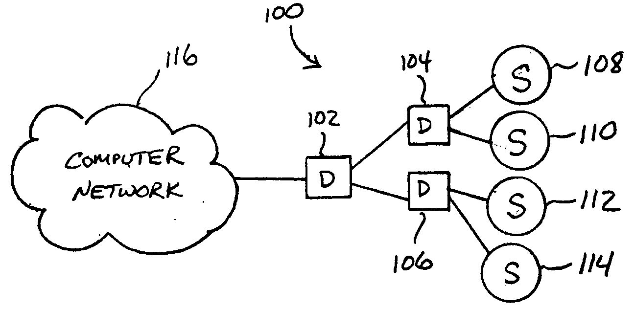
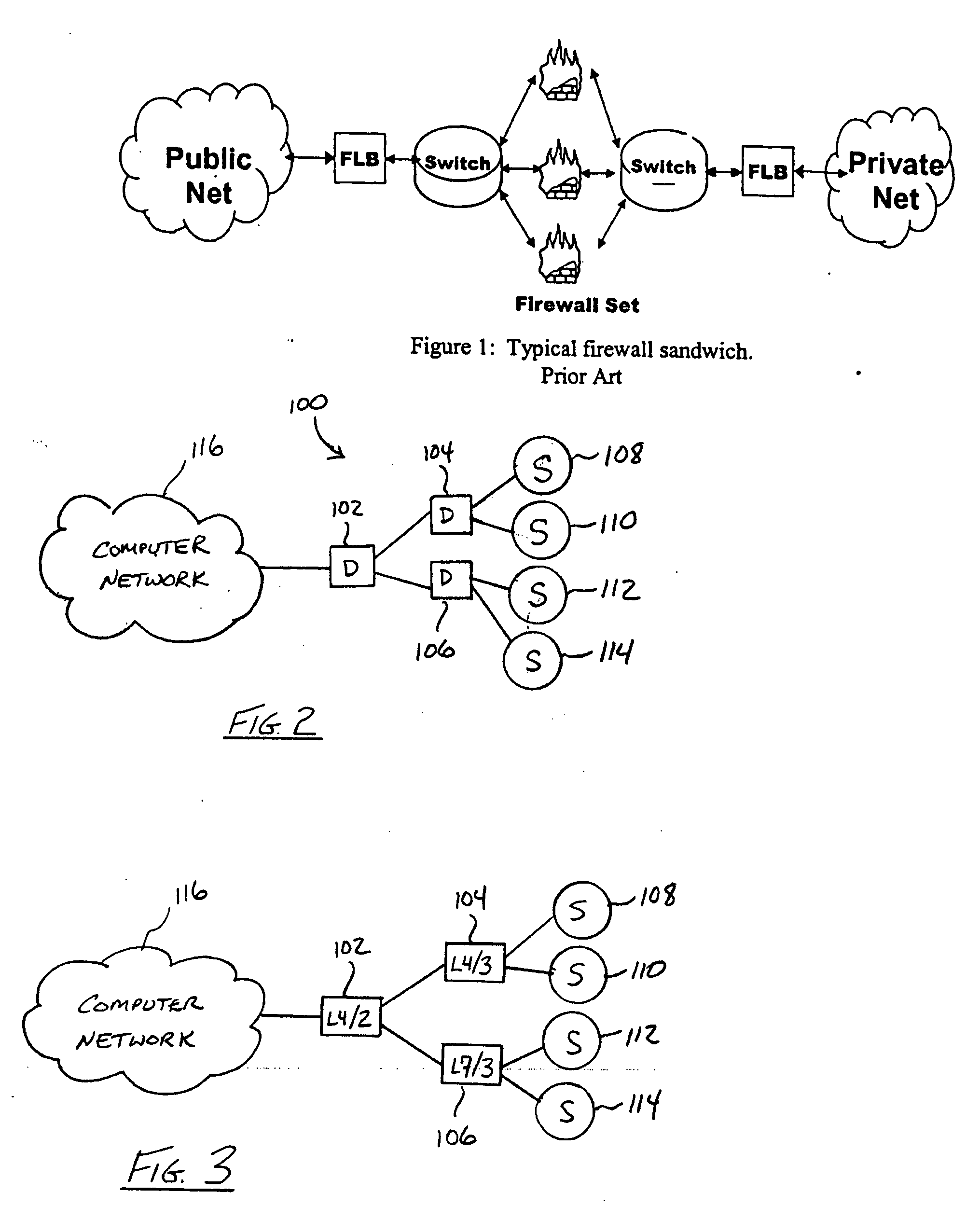
[0027] A cluster-based server system according to a first embodiment of the present invention is indicated generally as 100 in FIG. 2. As shown in FIG. 2, the system 100 includes multiple dispatchers 102, 104, 106 and multiple computer servers 108, 110, 112, 114 (also referred to as “back-end servers”). In this embodiment, dispatcher 102 is configured for sending packets received by the dispatcher 102 (e.g., packets received from the computer network 116 shown in FIG. 1) to one of the dispatchers 104, 106. Further, dispatchers 104, 106 are configured for forwarding packets received from the dispatcher 102 to one or more of the servers 108-114 for processing. In this manner, a highly scalable and configurable system 100 is advantageously provided, as further explained below.

[0028] In the embodiment of FIG. 2, dispatcher 104 manages a first set of servers 108, 110, and dispatcher 106 manages a second set of servers 112, 114, with dispatcher 102 forwarding packets received from the co...


PUM


Abstract

A secure cluster-based server system includes a plurality of firewalls, a plurality of back-end servers, a logically external firewall dispatcher, a logically internal firewall dispatcher, and a plurality of second stage dispatchers. The external firewall dispatcher is configured for routing packets received from the external network through one or more of the firewalls to the internal firewall dispatcher, the internal firewall dispatcher is configured for dispatching packets received from the one or more firewalls to one or more of the second stage dispatchers, and the second stage dispatchers are configured for dispatching packets received from the internal firewall dispatcher to one or more of the back-end servers for processing. A computerized method of interfacing an external network to a cluster-based server includes receiving packets from a plurality of firewalls with a first stage dispatcher, dispatching each received packet from the first stage dispatcher to one of a plurality of second stage dispatchers, and dispatching each packet received by one of the second stage dispatchers to one of a plurality of servers for processing.

Description

CROSS-REFERENCE TO RELATED APPLICATIONS [0001] This application claims priority to U.S. Provisional Application No. 60 / 523,858 filed on Nov. 20, 2003, the entire disclosure of which is incorporated herein by reference.BACKGROUND OF THE INVENTION [0002] A variety of servers are known in the art for serving the needs of millions of computer network users. More recently, cluster-based servers have been developed, where a pool of “back-end” servers are tied together to act as a single unit, typically in conjunction with a dispatcher that shares or balances the load across the server pool. While useful for a variety of server applications, cluster-based servers are often configured as Web servers for providing requested resources to users over the Internet. [0003] Server clustering technologies are broadly classified as: OSI layer four switching with layer two packet forwarding (L4 / 2); OSI layer four switching with layer three packet forwarding (L4 / 3); and OSI layer seven (L7) switching ...

Claims


Application Information

Patent Timeline
IPC IPC(8): G06F11/30
CPCH04L63/0218
Inventor GODDARD, STEPHEN M.
Owner BOARD OF RGT UNIV OF NEBRASKA
Features
  • Generate Ideas
  • Intellectual Property
  • Life Sciences
  • Materials
  • Tech Scout
  • Unparalleled Data Quality
  • Higher Quality Content
  • 60% Fewer Hallucinations
Learn More