Sensor testing system and method

a technology of sensor and test system, applied in the field of sensor testing system and method, can solve the problems of tire pressure but not robust, faulty readings, and generally relatively complex devices, and achieve the effect of preventing pressure leakag

Inactive Publication Date: 2005-08-25
HONEYWELL INT INC
View PDF13 Cites 8 Cited by
  • Summary
  • Abstract
  • Description
  • Claims
  • Application Information

AI Technical Summary

Benefits of technology

[0014] It is another aspect of the present invention to provide for a sensor testing method and system, which can be utilized to rest the effectiveness of surface acoustic wave (SAW) sensor devices.
[0016] Such a connector component can be formed as a BNC connector which attaches to a printed circuit board of the sensor to be tested, along with and a plurality of wires associated with the sensor. Each printed circuit board can include two female sockets soldered to the printed circuit board that respectively accept a pin associated with a base of the sensor. Additionally, each pressurized cavity among can be filled with an epoxy for sealing each respective housing component to the BNC connector to prevent pressure leakage. The epoxy can be configured as a high-temperature epoxy. The pressure rail can be configured from aluminum and can form, for example, an aluminum plate. Additionally, a plurality of O-ring grooves can be provided, wherein each O-ring groove is respectively milled about each pressurized cavity in order to seal the pressure rail to the housing components. Each pressurized cavity functions as a pressure channel that permits pressure to be applied in each of the pressurized cavities milled into the top surface of the aluminum plate.

Problems solved by technology

Such devices are generally relatively complex and expensive or alternatively are not particularly robust.
This system provides an indication of low tire pressure but is not robust.
For example mud or other debris on the wheels may cause faulty readings.
Clearly such a system simply cannot provide a reading of actual tire pressure.
However, if the tire in a rut or is parked on uneven ground, a faulty low-pressure reading is likely to be generated.
More complicated systems are capable of monitoring tire pressure.
Conventional wireless systems, however, are not durable and are expensive to design and produce.
The housing and base of the sensor must also not be placed into a condition in which an electrical short runs from the housing to the base, causing a frequency shift or error in the sensor measurements.

Method used


Image

  • Sensor testing system and method
  • Sensor testing system and method
  • Sensor testing system and method

Examples


Embodiment Construction

[0024] The particular values and configurations discussed in these non-limiting examples can be varied and are cited merely to illustrate at least one embodiment of the present invention and are not intended to limit the scope of the invention.

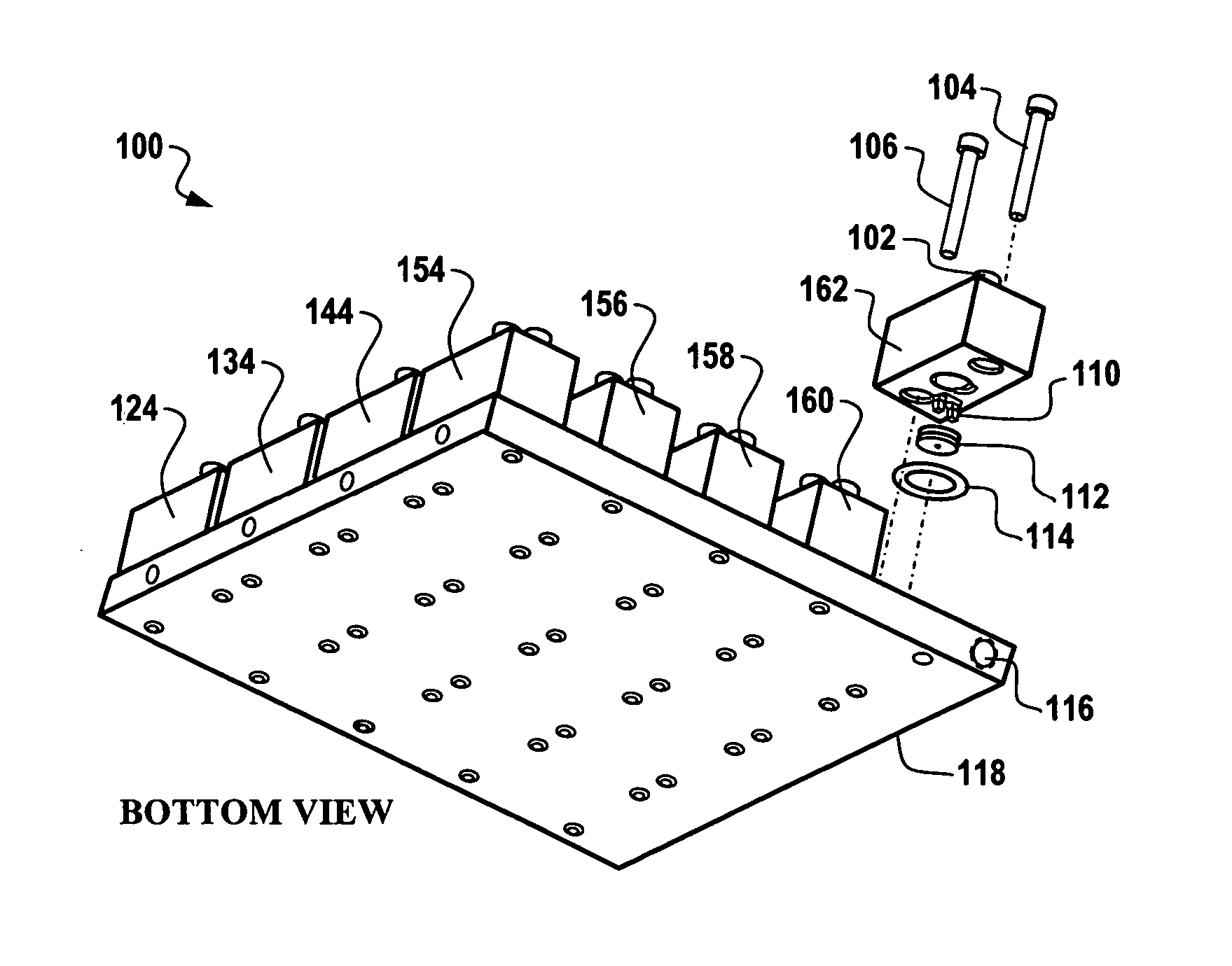
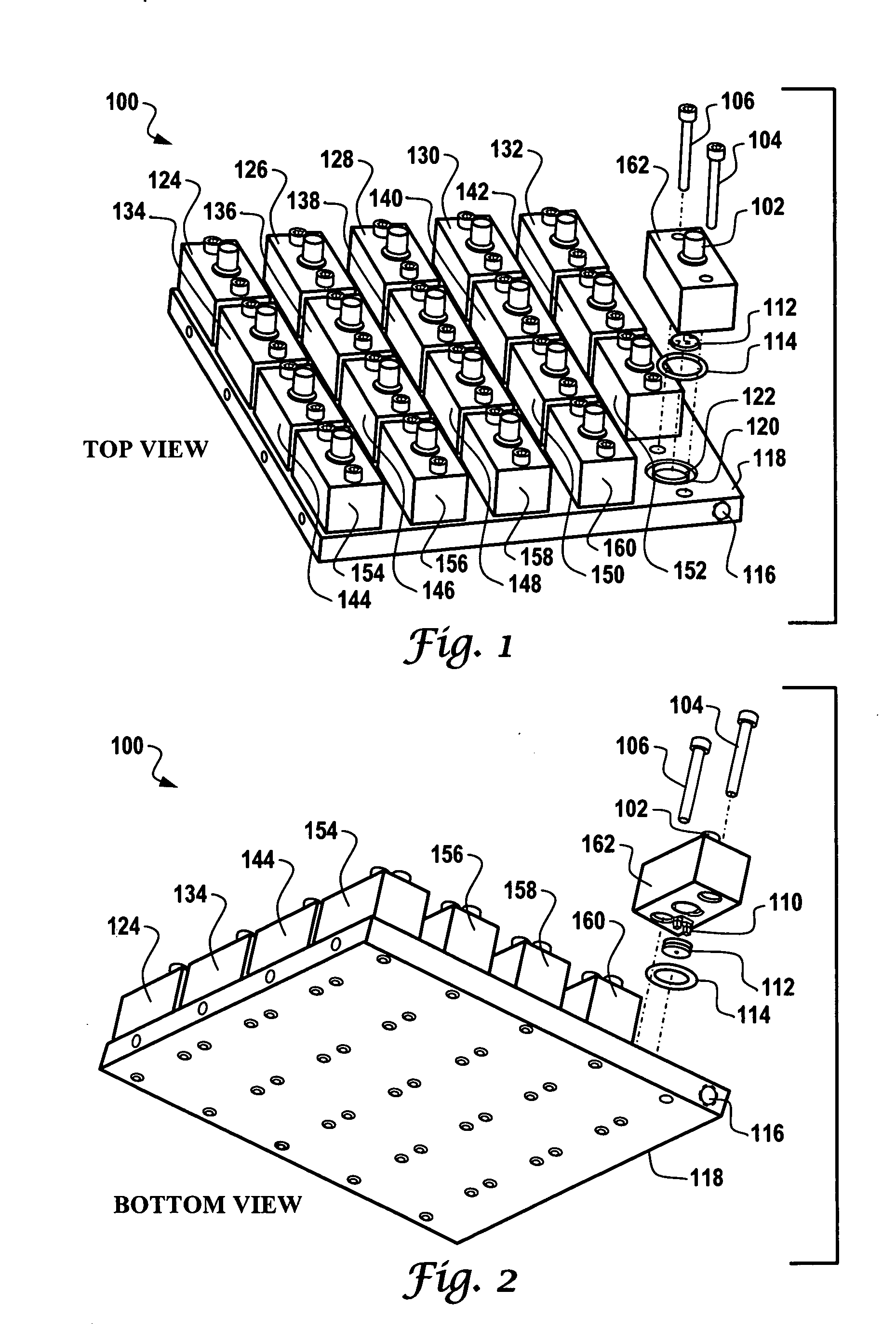
[0025]FIG. 1 illustrates a top perspective view of a sensor testing system 100, which can be implemented in accordance with a preferred embodiment of the present invention. FIG. 2 illustrates a bottom perspective view of the sensor testing system 100 depicted in FIG. 1, in accordance with a preferred embodiment of the present invention. Note that in both FIGS. 1 and 2, similar or identical parts or elements are indicated generally by identical reference numerals. System 100 generally comprises a pressure rail 118 having a plurality of pressurized cavities, such as cavity 122, formed therein. Pressure rail 118, which can be formed from aluminum, generally comprises one or more pressure inlets, such as, for example, inlet 116. Each inlet is for...


PUM

PropertyMeasurementUnit
pressureaaaaaaaaaa
temperatureaaaaaaaaaa
air pressureaaaaaaaaaa

Abstract

In general, a pressure rail can be provide, which includes one or more pressure inlets and a plurality of pressured cavities formed therein. Housing components can be respectively located atop the pressured cavities, such that each housing component is sealed to a respective pressurized cavity. A connector component can be threaded into the top of each housing component for attachment to a sensor (e.g., a SAW sensor) for testing thereof. Each housing component can be configured from a clear thermoplastic material, which protects the housing components from RF frequencies, and high temperature and pressure conditions.

Description

TECHNICAL FIELD [0001] Embodiments are generally related to sensing methods and systems. Embodiments are also related to pressure and temperature sensors. Embodiments are additionally related to surface acoustic wave (SAW) devices and sensors, and particular to SAW button sensors and testing techniques thereof. BACKGROUND OF THE INVENTION [0002] Various sensors are known in the pressure and temperature sensing arts. The ability to detect pressure and / or temperature is an advantage to any devices which are under constant temperature and which can be severely affected by temperature conditions. An example of such a device is an automobile tire, which of course, experiences variations in both temperature and pressure. Many different techniques have been proposed for sensing the pressure and / or temperature in tires, and for delivering this information to the operator at a central location on the vehicle so that he knows that a tire is at low or high air pressure. [0003] Such sensors gen...

Claims


Application Information

Patent Timeline
Patent Type & Authority Applications(United States)
IPC IPC(8): G01D18/00G01L9/00G01L27/00
CPCG01L27/007G01L9/0025
Inventor EISENHOWER, GARY W. JR.
Owner HONEYWELL INT INC
Why Eureka
Try Eureka