

Piezoelectric thin film device and method for manufacturing the same
a thin film, piezoelectric technology, applied in piezoelectric/electrostrictive/magnetostrictive devices, relays, generators/motors, etc., can solve the problem of small electromechanical coupling constant, difficult to correspond to recent higher usage frequency demands, orientation of piezoelectric films, etc., to achieve the effect of electromechanical coupling constan
- Summary
- Abstract
- Description
- Claims
- Application Information
AI Technical Summary
Benefits of technology
Problems solved by technology
Method used
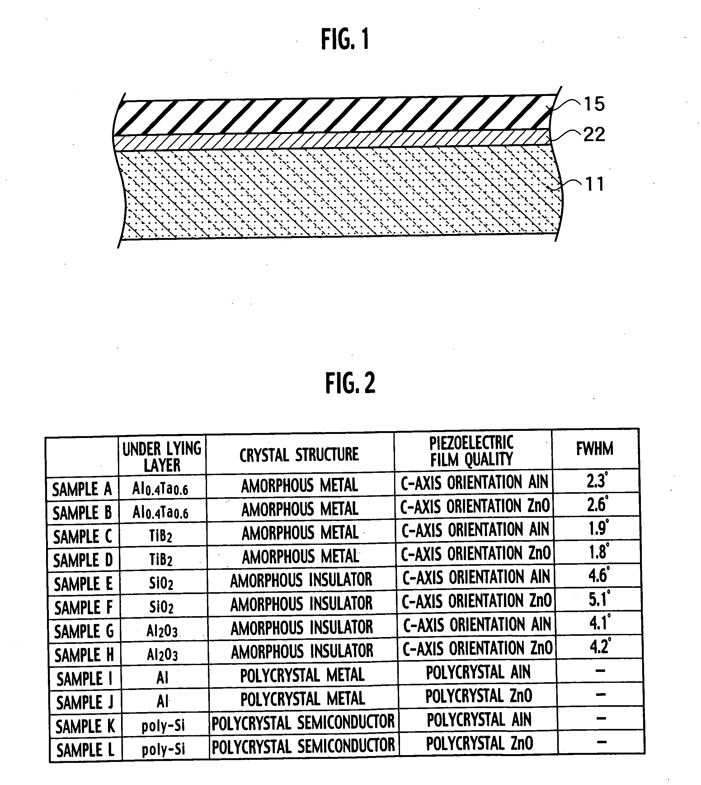
Image

Examples
first embodiment
[0061] An FBAR as a piezoelectric thin film device according to a first embodiment of the present invention includes a bottom electrode 14 of an amorphous metal film provided on a surface of a substrate 11, a piezoelectric film 15 provided on a surface of the bottom electrode 14, and a top electrode (top metal film) 16 provided on top of a surface of the piezoelectric film 15, as shown in FIG. 5. A resonator 20 is defined as a region in which the bottom electrode 14 and the top electrode 16 are facing each other, including the piezoelectric film 15 sandwiched by the facing bottom electrode 14 and top electrode 16.
[0062] Additionally, as shown in FIG. 6, a barrier layer 13 is provided surrounding a cavity 17 provided on top of the substrate 11. The resonator 20 is disposed on top of the cavity 17 so as to be projecting into a free space. The bottom electrode 14 is provided from the surface of the substrate 11 extending to the surface of the barrier layer 13. For example, the substra...
second embodiment
[0171] A variable capacitor as a piezoelectric thin film device according to a second embodiment of the present invention includes a piezoelectric actuator 40 and a fixed electrode 46, as shown in FIG. 56. As shown in FIG. 57, a fixed end portion (first end portion) 48 of the piezoelectric actuator 40 is held on an anchor 42 provided on a surface of an insulating film 32 on a substrate 11. A working end portion (second end portion) 49 of the piezoelectric actuator 40 is projecting into a free space so as to face the fixed electrode 46 placed on the surface of the insulating film 32.
[0172] The piezoelectric actuator 40 includes a bottom electrode 14, a piezoelectric film 15, a top electrode 16, and a supporting film. The bottom electrode 14 is provided to extend to a location above the fixed electrode 46 from a surface of the anchor 42. The piezoelectric film 15 is placed on a surface of the bottom electrode 14. The top electrode 16 faces the bottom electrode 14 to sandwich the piez...
PUM
| Property | Measurement | Unit |
|---|---|---|
| resistivity | aaaaa | aaaaa |
| gap distance | aaaaa | aaaaa |
| thickness | aaaaa | aaaaa |
Abstract
Description
Claims
Application Information