Power factor correction circuit

a technology of power factor and control circuit, which is applied in the direction of ac network circuit arrangement, ac network voltage adjustment, instruments, etc., can solve the problems of motor efficiency, power factor deterioration, power factor control, etc., and achieve the effect of preventing motor stalling or overheating, and reducing the measured time delay

Inactive Publication Date: 2005-08-25
WILLOUGHBY BRIDGET
View PDF1 Cites 24 Cited by
  • Summary
  • Abstract
  • Description
  • Claims
  • Application Information

AI Technical Summary

Benefits of technology

[0006] A mid-point between each pair of the timed events is designated as a peak of the voltage waveform. The process is repeated for the AC current waveform and the corresponding peaks of the current waveform identified. The time delay between a designated peak of the voltage waveform and a designated peak of a corresponding half-cycle of the current waveform is representative of the power factor of power supplied to the load and the applied voltage is adjusted in a manner to bring the power factor towards unity, i.e., by reducing the measured time delay. The system also monitors peak values of the AC current and limits the power factor adjustment to prevent peak current values from falling below a selected minimum value so as to prevent motor stall or overheat. Typically, the adjusting process removes voltage from the load for a portion of each half-cycle of the AC voltage waveform either by gating the triac out of conduction at beginning or end of a half-cycle or by pulse width modulation.

Problems solved by technology

The motor is, therefore, inefficient at light load and power factor deteriorates.
A disadvantage of the prior art circuits for power factor control is the necessity of identifying the zero crossings of voltage and current.
In many instances the current in the AC motor is characterized by noise and other oscillations which may create multiple zero crossings each time current reverses.
Such current variations are reflected onto the voltage waveform and can provide similar difficulty in identifying a true zero crossing.
As a consequence, circuits for determining current and voltage zero crossings may be more complex than desired and increase the cost of implementing power factor controls.

Method used


Image

  • Power factor correction circuit
  • Power factor correction circuit
  • Power factor correction circuit

Examples


Embodiment Construction

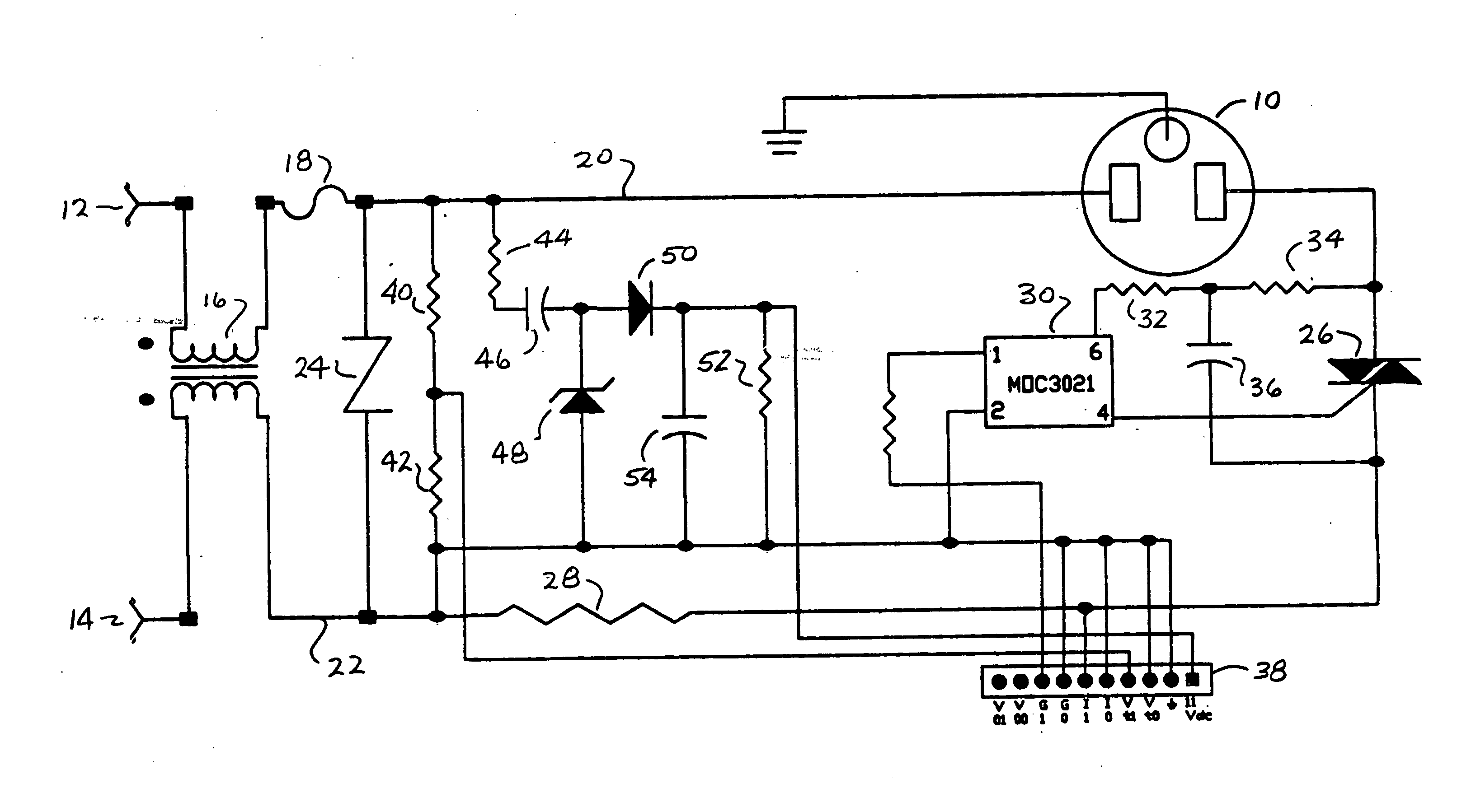
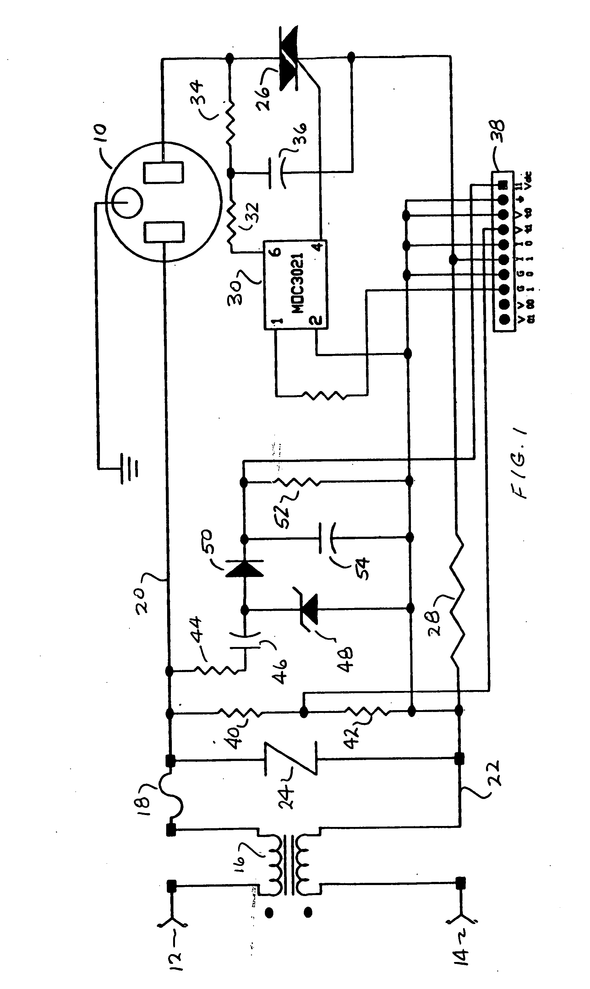
[0013]FIG. 1 is a schematic representation of an alternating current (AC) power control circuit for supplying power to an AC load 10 which may be, for example, an AC induction motor. While the invention will be described in terms of a single-phase load 10, it will be apparent that the invention is equally applicable to multi-phase applications such as, for example, a three-phase AC motor. In the circuit of FIG. 1, AC power from an external AC source such as an AC utility power connection is applied to terminals 12 and 14 and coupled through a toroidal coil inductor 16 and series fuse 18 to a pair of AC power buses 20, 22. An over voltage protection device such as a metal oxide varistor (MOV) 24 is connected between the buses 20 and 22. The bus 20 is connected to the first terminal of the load 10 while the bus 22 is connected to a second terminal load 10 through a series electronic switching device such as a triac 26. The circuit also includes a current sensing resistor 28 connected ...


PUM


Abstract

The present invention is illustrated in a method of power factor control for a power regulation system connected for supplying electric power to a reactive load. The system includes a microcomputer for supplying gating signals to an electronic switching device such as a triac for controlling the conduction phase angle of the triac to control the application of alternating current (AC) electric power to the load. The method comprises monitoring of the waveform of the AC voltage applied to the load and determining for each of the half-cycles of the waveform a timed event when the absolute value of the magnitude of the waveform transitions through a reference magnitude. A peak of the voltage waveform is determined. The process is repeated for the AC current waveform and the corresponding peaks of the current waveform identified. The time delay between a designated peak of the voltage waveform and a designated peak of a corresponding half-cycle of the current waveform is representative of the power factor of power supplied to the load and the applied voltage is adjusted in a manner to bring the power factor towards unity, i.e., by reducing the measured time delay. The system also monitors peak values of the AC current and limits the power factor adjustment to prevent current values from falling below a selected minimum value so as to prevent motor stall or overheat. Typically, the adjusting process removes voltage from the load for a portion of each half-cycle of the AC voltage waveform either by gating the triac out of conduction at beginning or end of a half-cycle or by pulse width modulation.

Description

BACKGROUND OF THE INVENTION [0001] The present invention relates to power factor control circuits for alternating current reactive loads and, more particularly, to a low cost power factor control circuit for AC induction motors. [0002] Power factor control circuits are well known in the art and are used to improve efficiency of AC motor drives. In particular, AC induction motors generally operate at a speed which is related to the frequency of the applied excitation and independent, within limits, of the applied voltage and load. Accordingly, under light load conditions, the motor can run at constant speed but draw more current than is actually required to produce power to drive the light load. The motor is, therefore, inefficient at light load and power factor deteriorates. The practical solution to improve efficiency, i.e., power factor, is to adjust the voltage applied to the motor so that the applied voltage is a function of loading. Most AC motor power factor control circuits a...

Claims


Application Information

Patent Timeline
Patent Type & Authority Applications(United States)
IPC IPC(8): G05F1/70
CPCG05F1/70
Inventor PIPPIN, WILLIAMPILLEGGI, NICHOLAS D.
Owner WILLOUGHBY BRIDGET
Why Eureka
Try Eureka